This chapter deals with the tooling for metal injection molding (MIM) parts. The intention is to provide the MIM process engineer with a basic understanding of the design options for MIM tooling. This should enable him to communicate with the tool designer on a deeper level of understanding. For more detailed information about MIM tooling, he should refer to the vast choice of specialist literature devoted to plastic injection molding tooling, which for the most part is also valid for MIM. First of all, the process engineer should be familiar with the basic design and the main functions of an injection molding machine. These features are introduced in Section 5.2. The next step is the knowledge of the elements of a tool set, as outlined in Section 5.3. On the basis of this knowledge, the various general mold design options are described in Section 5.4. This includes mold materials, oversize design, gating options, and venting. The design for undercuts involving the use of lifters, threaded and collapsible cores is also part of this section. Special features like hot runner molds and instrumentation are included in Section 5.5 and finally Section 5.6 gives some information about available supporting software and economic aspects.
Corresponding to the great importance of injection molding technology in modern manufacturing industries, the choice of injection molding machines worldwide is immense. In spite of the substantial differences in the design of injection molding machines from various suppliers, all of them have certain general design features in common which are necessary to carry out and control the injection molding process. The essential components are the injection unit and the clamping unit, see Fig. 5.1. The tooling is attached to the clamping unit.
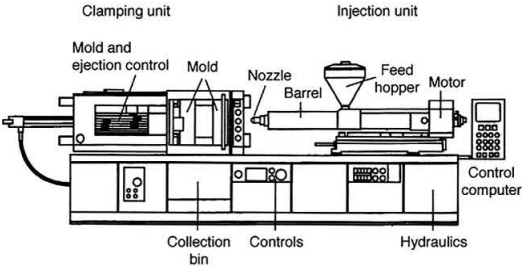
Fig. 5.1 General design of an injection molding machine.
The injection unit and clamping unit are usually arranged horizontally, as shown in the schematic picture. This is generally the most convenient way to produce MIM parts in a fully automatic way. Many machines allow the injection unit and the clamping unit to swivel to a vertical position. Then it is possible to load inserts into the mold and parts will not fall freely after ejection. This may be advantageous for From ASM. (2008). ASM handbook, Vol. 7, Powder metal technologies and applications. Materials Park, Ohio, USA: ASM International, p. 358. Reprinted with permission from ASM International. All rights reserved.
The whole machine is mounted on a rigid frame. A hydraulic pressure supply provides the necessary power to close the clamping unit and keeps it closed against the pressure of the feedstock in the mold. In fact, the maximum clamping force is the main characteristic by which the power and size of an injection molding machine is defined.The other drives of the machine are usually electric. There are also machines on the market which are fully electric.
Control instruments for pressure and temperature serve to monitor the process and a computer controls the operation of the machine. The collection bin under the mold can either be used to collect the products falling out of the mold, or a basket or conveyor belt or pick-and-place handling system may be installed.
The injection unit is essentially a heated barrel with a screw or plunger transporting the molten feedstock to the injection nozzle at the end pointing towards the clamping unit. The screw or plunger is driven by the motor at its rear end.
Feedstock granules are fed into the heated barrel through the hopper. Inside the barrel the feedstock is then heated, compressed, homogenized, and finally injected into the mold cavity. The barrel is usually equipped with a screw along its axis, which exerts a forward movement on the feedstock when rotating. A metering valve at the front end separates the exact amount of feedstock for the next shot from the reservoir inside the barrel. The molten feedstock is injected into the mold through a nozzle at the hot end of the barrel.
The control computer of the machine allows the barrel temperature to be adjusted in several independent zones. The first heated zone serves to melt the feedstock quickly, as the abrasiveness of the molten feedstock is much less than that of the solid granules. In the following zones, the temperature is gradually increased and homogenized inside the barrel.
An elevated barrel temperature is required for melting the feedstock and the action of the screw exerts pressure and torque on the feedstock that brings it to the optimum viscosity. If the temperature is too low, the feedstock may freeze before the mold cavity is completely filled. An excessively high-temperature leads to a very low viscosity that will cause problems, such as molten feedstock dripping out of the nozzle opening, increasing formation of flash due to binder squeezing out through gaps between mold parts, prolonged cooling times, and so on. Therefore the barrel temperature will be kept as low as possible,just to have enough heat to securely fill the mold cavity. It should also be consideredthat some heatis generatedinthe barrel bythe frictional forces between screw and feedstock, so not all of the heat that is required must be introduced from outside.

Fig. 5.2 Schematic diagram showing profile and cross sections of a feed screw (Arburg).
The screwis usually designed with a reduction ofthe feedstock volume whileitistransported forward. A schematic diagram of the screw profile is shown in Fig. 5.2. The feedstock enters the feed zone andis heated and plasticized there. Theturning screw transports the feedstock towards the compression zone where the reducing cross section causes the compression. The third section is the metering zone where a further homogenization is achieved. The feedstock is intensively sheared, homogenized, and compressed by the turning screw. The rotation of the screw determines the pressure inside the barrel, and a forward and backward movement of the screw serves to inject a well-defined quantity of feedstock into the mold with each molding cycle. A nonreturn valve at the front end of the screw prevents molten feedstock from being pressed back into the barrel.
In its simplest form, a tool set for powder injection molding looks as shown in Fig. 5.3. It is composed of a set of steel plates and has clamping plates at both ends. The front clamping plate is firmly attached at the side facing the injection unit; it is sometimes referred to as the stationary plate. This has a central hole surrounded by a locating ring where the nozzle of the injection unit is centered when the feedstock is injected into the mold through the sprue bushing. Two cavity plates behind the front clamping plate contain one or more mold cavities which are machined into the space between them. The front cavity plate is stationary together with the front clamping plate and the rear cavity plate is attached to the rear clamping plate. The stationary side of the mold is known as the A side, and the moving side is known as the B side.
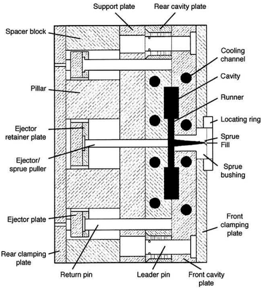
Fig. 5.3 Basic elements of a tool set for metal injection molding.
From ASM. (2008). ASM handbook, Vol. 7, Powder metal technologies and applications. Materials Park, Ohio, USA: ASM International, p. 357. Reprinted with permission from ASM International. All rights reserved.
The temperature of the mold cavities is controlled by means of hot water or oil, which is circulated through cooling channels inside the cavity plates. The proper design of cooling channels and the optimum mold temperature depend largely on the type of feedstock and require some experience. It is impossible to give any general guidelines. The mold temperature must be low enough to freeze the feedstock quickly and high enough to allow all mold cavities to be completely filled before the feedstock starts to freeze. The BASF Catamold typically uses oil heating because of its high-temperature requirement, whereas wax/polymer and water-soluble systems typically perform well with water temperature control.
The cavity plates are closed during molding, then separated from one another after the molded parts have solidified so that the parts can be ejected. Mold cavities should be so designed that the adhesive forces are higher at the rear cavity plate than at the front plate. In this way, the molded parts will stick to the rear plate when the plates are separated and can be ejected by the ejector pins; otherwise, the parts will not fall off the mold. Some tools have spring-loaded ejector pins in the A side to ensure that the parts remain on the B side when the mold opens.
While the front cavity plate is firmly attached to the front clamping plate, the rear cavity plate is held in position by the support plate. It is connected to the rear clamping plate by the spacer block. The exact position of the two cavity plates when the mold is closed is guaranteed by four leader pins at the corners of the tool set. Holes in the spacer plate leave room for moving elements such as ejector pins and return pins. Their ends are attached to the ejector plate, which moves inside the spacer plate, and they are held in place by the ejector retainer plate. Depending on the size and quantity of the molded components, several ejector pins may be required. The central ejector pin serves to pull the sprue out of the sprue bushing when the parts are ejected.
The decision about the number of ejector pins and their position is made by the mold designer on the basis of an analysis of the adhesive forces between mold and part. This includes consideration of the shrinkage during cooling. Owing to this shrinkage, parts will generally be released easily from their outer contours, but may stick on inner contours. Areas with great adhesion can be flat surfaces or complex geometries.
Mold release may be supported by draft angles. These are angles on surfaces which are parallel to the direction in which the mold opens. An angle of 1 degree is usually sufficient.
The basic elements that form part of each injection molding tool set have been introduced. Most of these components are standardized and can be purchased at moderate cost from specialist suppliers. MIM parts manufacturers rely on these suppliers to save costs and maintain a high-quality standard of their molds. Only the mold cavity plates must be custom-manufactured.
For more complex part geometries, the mold cavities may include cores, retractable slides, threads, etc. An additional plate between the two cavity plates is sometimes introduced that provides more flexibility to position the gate or gates. These are the so-called three-plate molds; for example, a gate position in the center of the part requires a three-plate mold.
Although injection molding of MIM feedstocks is generally very similar to injection molding of thermoplastics, a few differences should be kept in mind when talking about mold design. MIM feedstock is brittle and often sticks to the parting line. Therefore, MIM tools need to be tighter than tools for plastic injection molding to prevent flashing.
MIM powders are not compressible and therefore MIM feedstocks are often more abrasive in the injection molding process as compared to regular thermoplastic materials. The feedstock may further damage the mold in the parting line with repetitive mold opening and closing. Consequently, there is an increased risk of erosion in the mold cavities and also in the barrel of the molding machine. Preventive measures are wear resistant coatings inside the barrel and on the screw surface and the use of highly wear resistant materials like tool steels and cemented carbide for all tool parts that are in direct contact with the feedstock.
The significant shrinkage of MIM components in the processing steps following injection molding, i.e., during binder removal and particularly during sintering, must be anticipated in the mold dimensions. The shrinkage is empirically determined as the linear shrinkage of a rectangular bar 26–30mm long and 4–6mm wide, with dimensions given for the mold cavity. When the length of the mold cavity L0 and that of the sintered bar L have been measured, the shrinkage δ can be calculated as

The value of δ is usually multiplied by 100 to give the shrinkage in percent. While the shrinkage is a characteristic of the material, tool designers prefer to use the tool cavity expansion factor Z, which is given as the ratio of the mold dimension L0 and the final part dimension L.

Since these two parameters are very similar mathematically, care should be taken not to confuse them. It should be noted that the shrinkage δ is related to the dimension of the mold cavity L0 and the cavity expansion factor Z is related to the final part dimension L. As the part dimension is always smaller, the cavity expansion factor suggests a larger shrinkage than there really is. For example, a cavity expansion factor of Z¼1.18 would correspond to a shrinkage of δ¼15.25%.
The tool cavity expansion factor Z can be calculated from the shrinkage according to

By using the expansion factor, the mold designer will expand all linear dimensions and radii according to L0¼Z * L. Angles are not generally changed. Outer dimensions are initially set to the lower end of the tolerance band and inner dimensions to the upper end.
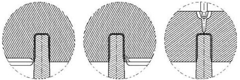
Fig. 5.4 Tab gate (left), subgate (center), and three-plate tool (right) (dynamic).
Then, it is possible to correct the mold cavity when the first samples have been sintered and to allow for some tool wear. This is also known as “steel-safe” condition. Fine tuning of the mold dimensions is often necessary when close part tolerances are required.
The sprue is a conical channel of typically around 6mm diameter with a taper of 5 degrees through which the feedstock enters the mold. The feedstock speed is reduced by the growing diameter. At the end of the sprue there is a small recess where the front of the feedstock stream, which has already cooled off, is deposited. From here the runners branch off to the sides. A continuous flow is achieved if the total runner cross section is similar to the maximum sprue cross section. The runner design and the position of the mold cavity, or cavities, should be such that the forces exerted on the mold by the feedstock are symmetrical with respect to the central axis of the mold in order to minimize the formation of flash.
The point where feedstock enters the mold cavity is called the gate. This is the point with the smallest cross section in the entire tooling system and the highest flow speed and pressure. One or more gates may be designed on each mold cavity.
The gate position is the most important measure to control the flow of molten feedstock inside the mold cavity. Since the runner is usually in the mold parting plane, the easiest option is to place the gate in the parting plane as well. This is the tab gate, see Fig. 5.4. The flow of material should be directed against an opposing wall so that the feedstock fills the cavity continuously without jetting. Also it should be designed at the thickest section of the part so that the cross section of the feedstock stream always remains constant or diminishes. If the cross section increases, the pressure in the mold and flow speed will drop dramatically so that it becomes difficult to fill the cavity completely without defects.
The jetting phenomenon occurs where a liquid leaves containment at high speed under high pressure into a free space; in everyday life, for example, it is known as the garden hose effect. The liquid is dispersed into fine droplets. If this occurs in the mold, the molded parts will most likely contain air bubbles which lead to internal defects after sintering, weld lines, and surface defects. This must be avoided by all means.
The gate can be displaced from the parting plane up to several millimeters by designing a short channel through the cavity plate. This is the subgate, also known as the tunnel gate. Subgate channels cannot be longer than a few millimeters because the feedstock freezes very quickly in such a small cross section. If the gate is required at a great distance from the parting plane, three-plate tooling is necessary. Runner and gate are then led to the mold cavity through the third plate. The three-plate tooling has the additional advantage that the sprue and runner are automatically sheared off and separated from the parts when the parts are ejected.
When several gates are designed on a part, the molten feedstock enters the mold cavity from all gates simultaneously. This reduces the time required to fill the mold cavity, but also imposes risks on the part quality. Where two streams of feedstock unite, the frozen front areas may not completely weld together. The result is a so-called weld line at the part surface. Weld lines are often only an optical deficiency as long as the feedstock welds together perfectly, but they may also be indicative of internal defects.
Multiple gates are particularly recommended if there is a risk that the feedstock could freeze before the cavity is entirely filled, i.e., if the flow path is long and/or the wall thickness is small. The gate positions must ensure that the various streams of feedstock completely unite without weld lines and without trapping air.
The sprue and runner material can be easily broken off at the gate and separated from the compacts. Nevertheless the parts will exhibit some irregularity at the fracture surface. If possible, the part surface at the gate should be designed a little lower than the neighboring surface so that it does not impede the function of the part. If this is impossible, the gate area must be mechanically flattened on the green part after injection molding.
The mold parting line is the trace left on the molded part where the two cavity plates are separated. The mold designer will try to place the parting line so that the function of the component is not negatively affected. In some cases, it is essential to remove the parting line mechanically for functional or aesthetic reasons.
The mold cavity is filled with air when the feedstock is pressed into the mold.Proper venting is therefore very important; i.e., the mold designer has to foresee ways for the air to leave the mold. Air can often escape through the clearance between ejector pins and the cavity plate or in the parting plane and elsewhere, but if necessary venting channels 0.005–0.01mm deep are ground into the parting plane.
A thorough understanding of the feedstock flow in the mold cavity is necessary for proper design of gates and vents. Vents should preferably be at the ends of the cavity which are filled last. If air is trapped inside the mold cavity, it cannot be completely filled with feedstock.
Gaps and vents do not only perform the useful function of letting air out of the mold, they also provide opportunities for the feedstock to squeeze out. The result is flash formation on the green parts, which is undesirable and necessitates additional work such as subsequent deburring. Wherever possible, all necessary secondary operations are usually done on the green part rather than on the sintered component because the green parts are much softer and easier to process.
Undercuts in MIM parts require mold elements that move in a direction lateral to the opening movement during the ejection procedure. This can be achieved by angle pins which are attached to the front clamping plate. An example is shown in Fig. 5.5. When the mold is opened, which here is in the vertical direction, the block with the angle pin is forced to move sideways and the part with an undercut is released and can be ejected.
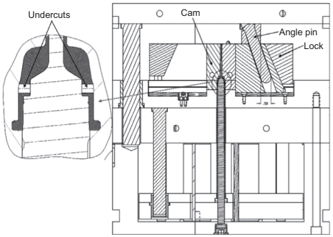
Fig. 5.5 Undercuts can be shaped by laterally moving elements (dynamic).
Another option to produce parts with an undercut is to attach the angle lifter to the ejector plate and let it travel forward with the ejection movement, as shown in Fig. 5.6. The end of the lifter forms the undercut and moves sideways with the ejection movement so that the part is released.
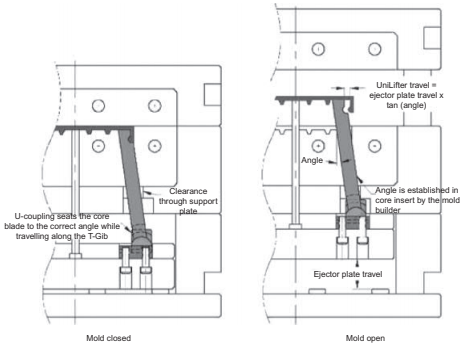
Fig. 5.6 Angle lifters for shaping undercuts (dynamic).
The principle of lateral motion of tool parts under a slight angle can be applied in many ways. Fig. 5.7 shows an example of a lifter composed of two halves which are attached to the ejector plate. When the lifter moves upward during ejection, the two halves approach each other and set the part free.

Fig. 5.7 Part with undercut (left) and mold design (dynamic).
Even more complex internal geometric features, including undercuts, are possible with collapsible cores. These are relatively complex tooling elements which collapse when their inner support elements are withdrawn. The core shown in Fig. 5.8 is composed of an inner supporting element and six outer elements. When the mold is opened, the inner support is withdrawn and the outer elements move inwards and release the part. Undercuts up to 12% are generally possible with these cores, in some cases even 17%.
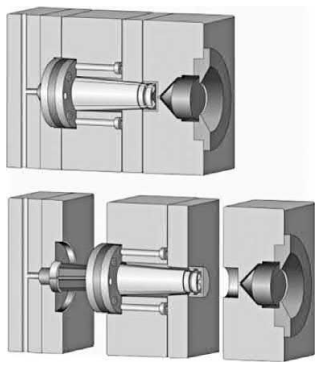
Fig. 5.8 Collapsible core in molding (top) and ejection position (bottom) (Wiedemann).
Internal threads in MIM parts are shaped by means of threaded core rods. These are unscrewed before the part is ejected from the mold. An example is shown in Fig. 5.9 for a multiple cavity tooling. The set of threaded cores can be unscrewed simultaneously with a gearbox, as shown in Fig. 5.10.
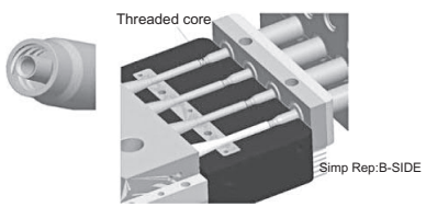
Fig. 5.9 Part with inner thread (left) and threaded cores in a mold with four cavities (dynamic).
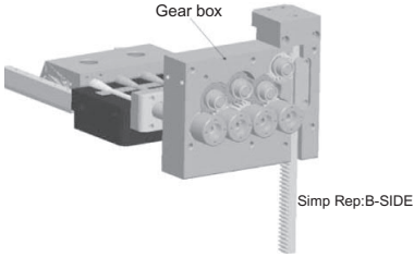
Fig. 5.10 Earbox for synchronized unscrewing (dynamic).
The stream of feedstock entering the mold can be imagined like a stream of lava flowing down a volcano. The inside is liquid and the surface, which is in contact with the environment, is solid. When the feedstock comes into contact with the cool walls of sprue and runner, a thin skin of frozen feedstock is immediately formed. The hot, molten feedstock then flows in the core of the runner channel. The frozen skin eventually grows thicker, the cross section of the molten core is reduced, and the resistance against a further supply of feedstock increases. When the cross section of the runner is entirely frozen, it is impossible to further sustain the injection pressure inside the mold.
A more advanced technology uses electrically heated hot runner nozzles to keep the feedstock temperature in the entire feeding system permanently above the freezing point. Hot runner nozzles are premanufactured components which are integrated into the mold. They are equipped with a power supply and a thermocouple for temperature control. Besides single nozzles, as shown in Fig. 5.11, manifolds are also available, for multiple cavity tooling.
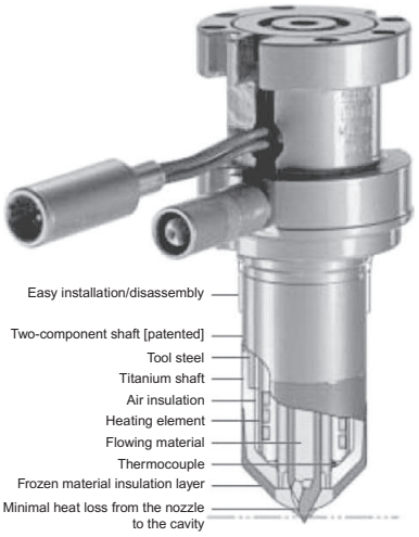
Fig. 5.11 Hot runner injection nozzle (G€unther Heißkanaltechnik).
Hot runner technology allows the injection pressure to be transmitted over a longer distance. The gate towards the mold cavity can be sealed with a needle after the cavity has been filled. The temperature distribution inside a hot runner mold must be carefully analyzed to make sure that the mold cavities are cool enough for the product to freeze quickly and still keep the runners liquid.
Hot runner molds have a special design at the injection side of the tooling, see Fig. 5.12, where the injection is from the top. The sprue is replaced by the hot runner nozzle, whose tip forms part of the mold cavity.
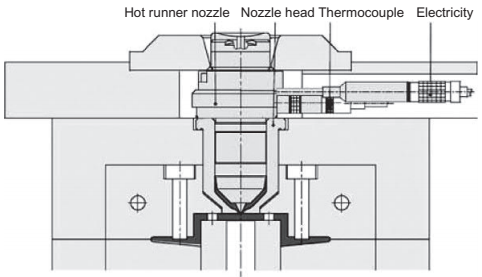
Fig. 5.12 Design of a single hot runner mold (G€unther Heißkanaltechnik)
In cold runner technology, the entire shot, that is the molded parts including runners and sprue, is ejected from the mold after it has frozen and the sprue and runner material is recycled (i.e., it is crushed and added to fresh feedstock). Hot runner molds are more expensive to manufacture, but allow savings by reducing the feedstock waste and sometimes reduce the molding cycle times because the mold cavity often freezes faster than the runners. The significantly higher cost is only justified, however, for very high-volume production.
The quality of MIM parts depends very much on the consistency of the injection molding process. It is therefore desirable to reduce variations in temperature and pressure in the mold as far as possible. In the case of multiple cavities, a symmetrical arrangement is preferred where the path of the feedstock to each mold cavity is the same. Sensors are available for the direct measurement of temperature and pressure inside the mold cavities. With feedback of this information to the control computer, the barrel temperature and injection pressure can be adjusted in order to keep the mold temperature and pressure constant within narrow limits.
In the mold making sector, the MIM industry can rely on the vast plastics injection molding industry and their suppliers. The resources of mold designers, mold makers, suppliers of standardized mold components, sensor elements and instrumentation, mold design software, simulation, and even calculation software are immense.
Although the parameters of the injection molding machine can have a significant influence on the part quality, the most important factor in the injection molding process for the quality of MIM products is certainly the quality of the mold, with the greatest consideration given to its design and manufacture.
For economic reasons, independent mold designers often work for plastic injection moulders and powder injection moulders at the same time, but they are not involved in the subsequent manufacturing processes. Therefore they usually do not receive direct feedback about the performance of their molds and cannot immediately react to any drawbacks of their tooling. In the long run, this may be a disadvantage for MIM. There is even a growing tendency to import dies and molds from countries with low labor cost. A recent survey of the Center for Promotion of Imports from Developing Countries (CBI) based in Rotterdam in the Netherlands stated that the demand for tooling, dies, and molds in Europe amounted to €11.6 billion in 2007 and 8.5% of all tooling was imported from developing countries in that year (CBI, 2009).
Mold fill studies based on computer simulation can be a valuable tool in mold design. This software must be specially adapted to MIM feedstocks because the high density of metal powder particles in comparison to the thermoplastic binder can lead to unexpected effects during injection molding. An experiment using a two-phase computer model to predict the stages of mold filling on a wheel of 50mm diameter found that the density was not uniform in the green compact. Plate 5.1 (see color section between pages 222 and 223) shows the part at 25%, 50%, 75%, and 100% mold fill. The different colors represent the volume fractions of powder in the feedstock. Higher powder volume fractions mean higher green densities.
This effect was interpreted as follows. The flow speed of the feedstock during injection is so high that a change in the direction of flow causes considerable forces on powder particles, owing to their high moment of inertia, and this leads to a powder/ binder segregation resulting in density variations in the green compact. The consequence of density variations is nonuniform shrinkage during sintering and therefore less dimensional accuracy on the sintered parts.
In many cases, economic aspects have a great influence on mold design as well. The number of mold cavities, use oil hot or cold runner mold, and other variables depend not only on technical considerations, but also on matters of economy and efficiency. The use of computer calculation software allows the tool manufacturing costs to be calculated depending on the number of cavities, instrumentation, and so on. The user can quickly assess the most economic combination of many parameters and even determine the required injection pressure, clamping force, and cycle time. Advanced mold calculation software delivers not only the costs of the mold, but also the most important molding parameters and the manufacturing costs of the injection molding step.
Contact: Cindy Wang
Phone: +86 19916725892
Tel: 0512-55128901
Email: [email protected]
Add: No.6 Huxiang Road, Kunshan development Zone, JiangsuShanghai Branch: No. 398 Guiyang Rd, Yangpu District, Shanghai, China