Thermal debinding is the widely applied method for removing the binders from the green component. The simplicity of the method, devices used, and its applicability for mass production to combine with the sintering operation has made thermal debinding the foremost method for polymer removal in industry. Even though the equipment used and the method of thermal debinding is fairly simple, the process itself is very complex. Polymer removal by burnout involves chemical and physical mechanisms. The chemical mechanisms occur because of the thermal degradation of polymer into volatile species-pyrolysis. The physical mechanisms involve diffusion of the volatile species to the surface of the compact, as well as changes in the polymerdistribution within the green body. Depending on the material, its thermal conductivity, porosity, pore size, and related features, it is possible for mass diffusion or thermal diffusion to be controlling steps. As a further complication, component heating depends on heat transfer and the reaction enthalpies associated with pyrolysis events, leading to thermal kinetic effects that couple to the chemical-physical aspects. During thermal debinding, the strength of the component decreases first due to thermal softening of the polymer and subsequently due to loss of the polymer. Simultaneously stresses (thermal, gravitational, and residual) act on the component, which can generate cracks or distortion as the polymer degrades. Apart from macroscopic defects, any microscopic defects caused during thermal debinding are exaggerated during the subsequent sintering process. Contrary to general impressions, sintering does not healdebinding defects, but instead tends to amplify those defects.
Improper thermal debinding can result in carbonaceous residues that usually degrade the mechanical, optical, thermal, magnetic, or electronic properties of the sintered component. To prevent the various defects, it is common practice to employ extremely slow heating cycles, with negative implications on equipment requirements, capital expenditures, and productivity; in several situations thermal debinding is a production bottleneck. On average, the cost is about $2.5 per kg (component mass, not binder mass) to remove the polymer from small injection molded components in a typical 8 hcycle. Curiously, the binder content in the component might be just 5–10 wt%, so the cost of its removal is roughly tenfold more than the cost of the binder.
Various modeling studies developed for thermal debinding of injection molded samples are based on two hypothetical porosity developments. In the first case, the polymer-vapor interface is modeled to recede in a linear way in the compact as the polymer is removed, resulting in a porous outer layer and a core with liquid polymer. This type of porosity structure is termed “shrinking undegraded core or series model” . In the second case, porosity is considered to form uniformly in the compact because of distribution of liquid polymer under the influence of capillary pressure. This type of configuration is termed “uniform distributed or parallel model.” The microstructure of the two porosity models is shown in Fig. 4.8. “Shrinking undegraded core structure” is considered appropriate for the thermal debinding in an oxygen atmosphere. In this case, the thermal debinding starts from the surface of the compact. The rate of thermal debinding depends on the exposed surface area and diffusion of oxygen in the compact. In the case of thermal debinding in neutral atmospheres, the absence of a well-defined liquid-vapor interface was experimentally observed. The microstructure change during the thermal debinding process using scanning electron microscope (SEM) technique is shown in Fig. 4.9. The formation of pendular bonds during softening of binder can be clearly seen in Fig. 4.9.
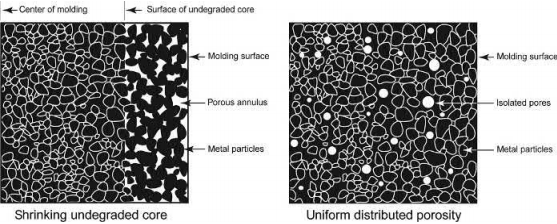
Fig. 4.8 Porosity structures used for modeling the polymer burnout process
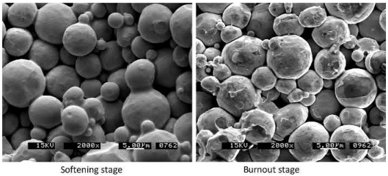
Fig. 4.9 Microstructure changes during thermal debinding process

where ε is the porosity in the agglomerate, H is the bonding force, and d is the diameter of the particle. The bonding force H is estimated from

where x is the average of the contact diameter between the particles. Taking the stress concentration factor into consideration, the strength of the agglomerate is given as

where K is the stress concentration factor and is obtained from

Suri et al. (2003) observed the morphology of agglomerates for powder injection molding feedstock of tungsten alloy powder mixed with a paraffin wax-polypropylene binder. The observations suggested that the average diameter of the contact between the particles (x) is 0.3 times the diameter of the particles (x¼3d). Using the same approximation, the value of green strength is estimated for carbonyl iron powder which was used as the candidate material to estimate the stresses developed in the compact during the thermal debinding process. The in situ strength of the carbonyl iron compact was estimated as 10.6MPa for ε value of 0.4. The in situ strength decreased to 0.79MPa with increase in ε to 0.9. The stresses in the compact simulated by Ying et al. (2002b, 2002c) were in the order of 10MPa due to polymer content change and 0.1MPa due to gas pressure and temperature change. The strength of the agglomerates as predicted by the modified Rumpf model is also in the same range as the stresses estimated by Ying et al. (2002b, 2002c). The analysis shows that modeling with the approach of in situ strength variation during thermal debinding is a promising way to develop heating cycles to minimize the formation of defects. The in situ strength of the compact is also expected to be dependent on the softening (viscosity) and burnout characteristics of the polymer. Thus the final equation for the in situ strength of the compact during the thermal debinding process should also include parameters based on the softening and degradation behavior of the polymer. Further research studies are required to finalize the model based on the in situ strength principle. These studies would require measuring in situ strength during the thermal debinding process and correlating measured values to the softening and burnout characteristics of the polymer.
Defect formation
Understanding the phenomena of defect evolution during thermal debinding and predicting critical heating cycles to avoid them has been the focus of research for many studies. A summary of the defects observed in various studies is listed in Table 4.6. These defects are more commonly observed during initial stages of thermal debinding for large-sized ceramic (small particle size) injection molding components. Several theories have been reported in the literature explaining the high probability of cracking during thermal debinding from ceramic injection molded components. These theories attribute the small particle size and brittle nature of the ceramics to the cracking tendency. However, none of the theories has been experimentally proven. The probable explanation of formation of defects in ceramics can be attributed to the angular shape of the particles. The angular shape restricts rearrangement of the particles under the influence of increase in internal pressure during thermal debinding. This results in further increase in internal pressures and cracking of the component. On the other hand, metallic particles are usually more spherical and rearrange (interparticle movement) under the influence of internal pressures and thus prevent the accumulation of high pressures and cracking of the component. Ceramic particles were found to serve as nuclei for heterogeneous bubble formation during thermal debinding. The molding pressure during injection molding was found to have an effect on bloating defect formation during burnout of ethylene vinyl acetate (EVA) from SiC particles. The bloating was proved to be due to acetic acid formed during degradation of EVA. The bloating was found to be absent in the case of samples shaped at high injection molding pressure. Several studies showed the beneficial effects of wicking prior to thermal debinding in reducing crack formation in samples. However, the beneficial effects of wicking were absent in case of large-sized components like turbine rotors, where the formation of cracking was found to be inevitable even at slow heating rates.
The requirement of extremely slow thermal debinding cycles (extending from hours to days) to successfully remove the polymer without forming defects can be acknowledged after noticing the heating rates at which defects were observed in various experimental studies (Table 4.6).
Table 4.6 Defects observed during the thermal debinding process
Ref. no | Materials | Sample shape and dimensions | Heating Rate (℃/min) | Defects | |
Powder | Polymer | ||||
26 | Al2O3 (0.53μm) | 40.2 vol% polymer mix of 4.60 wt% EVA (Elvax 250), 2.30 wt% EVA (Elvax 260), 4.60 wt% paraffin wax, 1.20wt% stearic acid, and 0.85 wt% oleic acid | Cylinder of 5.8mm diameter and 25mm length | 0.05, 0.2 | Bloating and cracking |
27 | Al2O3 (0.6μm) | 2wt% polystyrene and 12wt% paraffin oil | Square: 4×4mm2 | 2, 4.5 | Blistering, bloating and cracking |
3 | Al2O3 (0.6μm) | 50 vol% poly (α-methylstyrene) | Plates of 40mm×40mm×3.4&-2.9mm | 0.05-0.048 | Bloating and cracki |
28 | SiO2 | 35 vol% proprietary wax | 31mm diameter cylinder | 0.033 | Cracking |
29 | SiC (0.75μm) and minor additions of Al2O3 and Y2O3 | 49 vol% ethylene vinyl acetate (EVA) | Discs of 25.4mm diameter and thickness 0.5-8mm | 0.5, 2, 8 | Bloating |
30 | ZrO2 (0.25μm) | 50 vol% polymer mixture of paraffin wax, vinyl acetate and stearic acid (volumetric ratio of wax: polymer is 60:4 | Parallelepiped moldings 4×5×60mm | 0.5 | Cracking |
31 | Si3N4 6wt% Y2O3, 2wt% Al2O3 | 40 vol% polymer mix of 90wt% paraffin wax, 5wt% epoxy thermo setting material and 5wt% oleic acid | Turbine rotors | 0.17 | Cracking |
32 | AI | 35 vol% polymer mix of isotactic polypropylene, microcrystalline wax, and stearic acid | Bars 12.7mm×6.35×3,6mm | 0.02-2.1 | Bloating and cracking |
Carbon contamination
The residual carbon left in the component due to incomplete debinding was found to have an impact on the magnetic, electrical, mechanical, and sintered properties. The carbon content after thermal debinding was reported to be dependent on the following parameters:
the degradation behavior of the polymer;
interaction of polymer with the powder particles;
chemistry of the powder surface;
thermal debinding atmosphere;
oxidation temperature of the powder.
Low molecular weight polymers that degrade by evaporation and chain secession showed no carbon contamination. The carbon residue increases linearly with increase in molecular weight of the binders. The effect of the gaseous atmosphere (nitrogen, hydrogen, and a mixture of nitrogen and hydrogen) on the carbon residue and carbon content of Fe-2Ni steel has been reported. Thermal debinding of samples in a nitrogen and pure hydrogen atmosphere resulted in complete removal of polymer. However, addition of hydrogen to nitrogen resulted in incomplete burnout of polymer and carbon residue in the samples. Recombination of the burnout products in the presence of hydrogen was explained as one of the reasons for the increase in carbon content of the powder.
Some research studies have shown that the carbon residue in the burnout sample is dependent on the oxidation temperature of the powders . The carbon residue was reported to be a minimum in case of powders like silicon and alumina, which do not oxidize during the thermal debinding process. The high oxidation temperature of these metals has been reported to aid in effective conversion of carbon to volatile gases (Edirisinghe, 1991; Gillissen & Smolders, 1986). On the other hand, iron-based powders like low-alloy Fe-Ni, which undergo severe oxidation at low temperatures, have revealed residual carbon after the thermal debinding process. Excessive formation of oxides at the surface of the powder has been explained as one of the reasons for the carbon residue in these parts. It was hypothesized that the formation of oxides on the surface of the powders prevented easy out-gassing of the degraded polymer, resulting in carbon residue in the burnt out sample.
In general, it can be concluded that the residual carbon content in the burnout samples is primarily dependent on the degradation behavior of the polymer in the chosen burnout atmosphere. The low molecular weight polymers that degrade by evaporation or chain secession have the lowest probability of leaving carbon residue after the burnout process.
Distortion
Very few studies have been published in the literature regarding distortion or dimensional changes during thermal debinding. The in situ observation of shape loss during thermal debinding was recently published. The shape loss experiments were carried out using die compacted, gas atomized 316L stainless steel powders mixed with 1 wt% polyethylene co-vinyl acetate polymer and on injection molding samples made from gas atomized 316L powders, polypropylene, and polyethylene. The study showed that shape loss occurs primarily during the softening of the binder. The shape loss was also found to be dependent the degradation behavior of the binder. A recovery of shape loss was observed on burnout in the case of binders, which degrade, by formation of a double bond product. A recovery of shape loss was observed for gas atomized 316L powder and 1 wt% polyethylene covinyl acetate binder, as shown in Fig. 4.10. No recovery of shape loss was observed in the case of injection molding samples (Fig. 4.11). In this case, the samples broke after thermal debinding due to poor strength.
The total dimensional change during thermal debinding of injection molded SiC and EVA feedstock was modeled as the summation of extension due to thermal expansion and shrinkage due to loss of binder. The dimension change due to thermal expansion was estimated by the rule of mixtures (Hrdina & Halloran, 1998). Use of high solids loading, small particle size, and irregular shaped powders was suggested as an ideal combination to minimize distortion during thermal debinding. The study also suggested faster removal of polymer by applying a vacuum to minimize distortion. Increasing the heating rate was not suggested for faster removal of binder.Stated that most of the distortion during thermal debinding occurs due to flow by viscous creep during the softening of the polymer. Experiments were carried out with iron powders of different particle sizes and their binary mixtures. Interparticle friction between the particles was identified as an important factor for shape retention. The angle of repose at tap density (compacted angle) was correlated to the distortion behavior during thermal debinding. Based on their results, they recommended powders with a compacted angle over 55 degrees to minimize the distortion.
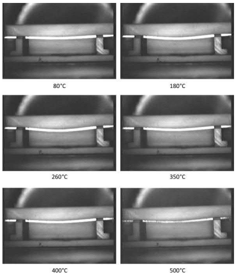
Fig. 4.10 In situ images during polymer burnout of samples made from admixed powders of gas
atomized 316L stainless steel and 1wt.% EVA
4.4 Mixing technologies
Various factors like particle size, shape, size distribution, and binder properties affect the mixing behavior of the feedstocks.
During the mixing process the large clusters of particles are initially broken down under the influence of shear action. As mixing is continued the clusters size decreases and the binder becomes dispersed in the interparticle pores. The homogeneity (M) of the feedstock is estimated based on the following equation

where MO is the initial mixture homogeneity, t is the time of mixing, and C and k are constants which depend on the powder and binder characteristics, agglomeration, and surface condition of the metal powder.
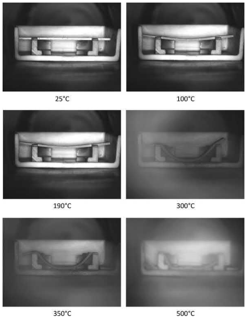
Fig. 4.11 In situ observation of shape loss during polymer burnout for injection molded samples made from gas atomized 316 L stainless steel and polymer mix of polypropylene and polyethylene
Typically the mixing process starts with heating the binder with a high melting point. Remaining constituents are added to the mix based on their respective melting points. The constituents are added according to progressively decreasing melting point. The metal powders are added once the binder constituents are mixed. The temperature of the feedstock decreases sharply with the addition of metal particles. The decrease in temperature is due to the high heat capacity of the binder. In some systems, the metal particles are added during the melting of the high melting point binders and before adding the low melting point components. This practice results in achieving a uniform coating of binder on the metal particles. The final mixing of the feedstock is carried out in a vacuum to degas the feedstock. The presence of air in the feedstock can result in the formation of defects during injection molding. The feedstock after mixing is discharged from the equipment and precautions should be taken to prevent segregation of the feedstock during this process. It is preferable to solidify the feedstock in the homogeneous condition. Continuous mixing of the feedstock during cooling can also result in obtaining an homogeneous feedstock. The temperature of mixing has to be chosen appropriately in case of thermoplastic binders. The temperature of mixing is carried out at intermediate temperatures. Mixing at low temperatures, at which the mixtures still possess high yield strength, will cause cavitation defects in the injection molded parts. Mixing at too high a temperature can result in binder degradation, resulting in a lowering of viscosity and separation of the powder from the binder.
The inhomogeneities in the MIM feedstock occur as a result either of the binder separating away from the metal particles or segregation of the metal particles in the binder. The size segregation of the particles is dominant in the case of metal powders with wide size distribution. During agitation, the smaller particles fill the interstitial pores between large particles resulting in segregation of powders. The segregation will be more in the case of larger particle size difference in the metal powders. Smaller particles size and irregular shaped metal particles due to higher interparticle friction will show low segregation. A binder with high viscosity can also lower segregation in the metal powders.
Smaller and irregular particles are more prone to agglomeration and require longer mixing times to obtain homogeneous feedstocks. The agglomeration of the particles also has a negative effect on the solids loading in the feedstock. The solids loading decreases from 0.67 to 0.37 for mono-sized spheres due to agglomeration. Addition of surface active agents to the binder system will prevent agglomeration of the feedstocks. A powder with wide particle size distribution will result in separation from the binder. The separation will be predominant in the case of a binder with low viscosity.
The variation of torque with mixing time of the feedstock is shown in Fig. 4.12. The initial torque is for mixing the pure binder. The torque continues to increase with the addition of metal particles. The increase in torque is due to a decrease in temperature of the feedstock because of the high thermal conductivity of the metal particles and an increase in homogeneities. The torque required for mixing decreases as the agglomerates are broken and liquid resulting from melting of the binder is released into the feedstock. The torque continues to decrease as a greater amount of liquid is released with continuous mixing. The torque reaches a steady state where the rate of mixing equals the rate of demixing. An homogeneous mixture will show a steady torque with mixing time.
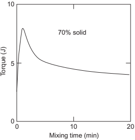
Fig. 4.12 Variation of torque with time of mixing
The viscosities of the feedstocks vary with the shear rate. The distance of the shear region in mixing will influence the homogeneity of the feedstock. Several high-shear mixer designs are used in MIM to obtain uniform distribution of shear rate and homogeneous feedstock composition. Some of the mixtures are single screw extruder, twin screw extruder, twin cam, double planetary, Z-blade mixtures, etc. Out of all the available mixtures, the twin screw extruder is most successful as it combines high shear rate and short dwell time at high temperature. The equipment consists of twin screws that counter rotate and move the feedstock through the heated extruder barrel. The discharge from the equipment is in the form of a uniform cylindrical product. The cost of the twin screw extruder is high and the double planetary mixer is mostly preferred as it provides a good balance of cost, quality, and productivity.
4.5 Case studies: Lab scale and commercial formulations
The examples of lab scale binder systems used for MIM are summarized in Table 4.7
Table 4.7 Examples of binder composition used in injection molding
Binder composition | Metal |
41.3wt% starch, 23.3wt% glycerol, 28.5 wt% linear low-density Polyethylene, 1.9 wt% citric acid, 5wt% stearic acid | 316L stainless steel |
45wt% low-density polyethylene, 55wt% paraffin wax, 5wt% stearic acid | 316L stainless steel |
45wt% low-density polyethylene, 45wt% paraffin wax, 10wt% stearic acid | 316L stainless steel |
30% paraffin wax, 10% carnauba wax, 10% bees wax, 45% ethylene vinyl acetate, 5% stearic acid | 316L stainless steel |
30% paraffin wax, 10% carnauba wax, 10% bees wax, 45% polypropylene, 5% stearic acid | 316L stainless steel |
25% paraffin wax, 20% carnauba wax, 20% bees wax, 25% ethylene vinyl acetate, 5% polypropylene, 5% stearic acid | 316L stainless steel |
64% paraffin wax, 16% microcrystalline paraffin wax, 15% ethylene vinyl acetate, 5% high-density polyethylene | 17-4 pH stainless steel |
63% paraffin wax, 16% microcrystalline paraffin wax, 15% ethylene vinyl acetate, 5% high-density polyethylene, 1% stearic acid | 17-4 pH stainless steel |
59% paraffin wax, 16% microcrystalline paraffin wax, 15% ethylene vinyl acetate, 5% high-density polyethylene, 5% stearic acid | 17-4 pH stainless steel |
55% paraffin wax, 16% microcrystalline paraffin wax, 15% ethylene vinyl acetate, 5% high density polyethylene, 9% stearic acid | 17-4 pH stainless steel |
50% high-density polyethylene, 50% paraffin wax | HS12-1-5-5 high-speed steel |
65% paraffin wax, 30% polyethylene, 5% stearic acid | Copper |
79% paraffin wax, 20% ethylene vinyl acetate, 1% stearic acid | Iron-nickel |
79% paraffin wax, 20% high-density polyethylene, 1% stearic acid | Iron-nickel |
79% paraffin wax, 10% high-density polyethylene, 10% ethylene vinyl acetate, 1% stearic acid | Iron-nickel |
85% paraffin wax, 15% ethylene vinyl acetate | 316L stainless steel |
65% paraffin wax, 35% ethylene vinyl acetate | 316L stainless steel |
70% paraffin wax, 5% stearic acid, 25% polyethylene | 316L stainless steel |
75% paraffin wax, 20% polyethylene, 5% ethylene vinyl acetate | 316L stainless steel |
75% paraffin wax, 15% polyethylene, 10% ethylene vinyl acetate | 316L stainless steel |
55% paraffin wax, 25% polypropylene, 5% stearic acid, 15% carnauba | Iron-nickel |
35% polypropylene, 60% paraffin wax, 5% stearic acid | W-Cu |
40% polypropylene, 55% paraffin wax, 5% stearic acid | W-Cu |


