Metal injection molding (MIM) is a process that utilizes the vast shape making capability of injection molding technology to manufacture structural metallic components. Unlike molding of thermoplastics where the molded component is often the final product, these components must subsequently be thermal processed to remove the polymers and sinter densified into structural components. Both thermoplastic and MIM processes utilize temperature and pressure to form components, thus, similarities in the science of shape forming exist between the two technologies. In this chapter, a review of the technology of injection molding is presented from the context of MIM. Where applicable, the similarities and contrasts with molding of thermoplastics will be discussed.
The following Sections 6.2-6.4 give an overview of the injection molding machines and tooling used and needed for the injection molding process. Emphasis on the reciprocating screw is given since this configuration dominates the industry.
The first injection molding machine was patented in 1872 by two brothers, John and Isaiah Hyatt. This machine was simple and utilized a plunger injection method to fill a cavity. This technology is still used today and is often referred to as low-pressure injection molding since this configuration can only produce low pressures during the injection step, as compared to a reciprocating screw configuration. This low-pressure or plunger method is utilized for powder injection molding (PIM) of ceramics and carbides. A wax-based binder system that has a low viscosity is used for low pressure PIM technologies. These low-pressure plunger machines are also used to form the wax patterns for modern investment (lost wax) casting. The initial capital cost and operating cost of these machines is lower; however, the productivity and dimensional repeatability are inferior to that of reciprocating screw technology. The first reciprocating screw was invented in 1946, by American inventor James Watson Hendry for processing thermoplastics. A combination of the screw and plunger technology exists in modern micromolding technology for thermoplastics and MIM. Although injection molding of thermoplastics is over 100 years old, the injection molding process was not recognized as a metal processing technology until 1979, when two design awards were given to MIM components; since then MIM has become one of the leading net-shape metal forming processes.
Metal and plastic injection molding use essentially the same type of machine to produce near net-shape components. The injection molding machine consists of an injection unit and a clamping unit. The injection and the clamping unit are actuated by hydraulic or electromechanical force depending upon make and model of the machine. Hybrid machines that combine hydraulic and electromechanical features also exist. Plate 6.1 shows a photograph of a typical hydraulic injection molding machine used for MIM.
The injection unit is composed of the barrel, heater bands, hopper, nozzle, screw, and screw tip. Fig. 6.1 shows the typical injection unit component configuration. The screw tip consists of a retainer, a check ring and rear seat, as shown in Fig. 6.2. The screw tip experiences significant wear and should be closely monitored for dimensional change, particularly on the check ring and the rear seat, which provides the seal to allow for injection at high pressures. These components are essential in providing a homogeneous feedstock to the melt delivery system of the mold. The injection unit should be sized so that the shot size is 20%-80% of the barrel capacity, but ultimately depends on the sensitivity of the binder system in the feedstock and the required volume to fill the part completely. This ensures that the feedstock has adequate time to reach equilibrium temperature and limits degradation of the binder system.
The clamping unit consists of the tie bars, platens, and ejection system. Some clamping units are designed without tie bars, which allows for larger tools to be utilized since the tie bars are absent from taking space on the platens. The clamping unit is where the mold is mounted to the injection molding machine. The tie bar spacing and platen size are the limiting factors in the envelope size of tool that can be utilized in a machine. Clamp tonnage is the limiting factor in how large of a component can be successfully run in the machine. If the machine clamping tonnage is too low, the component will flash. Flash can also be caused by a worn tool, a poorly fitted tool or some other process issue, such as too high an injection speed or pack pressure. Typical tonnage requirements are about 8-10 tons per square inch of projected area of runner and part. MIM components are typically made on presses in the 100 ton or lower range; however, larger presses can be used in special applications.
The most significant differences between the plastic injection molding machine and the MIM machine are in the injection unit and control system. The screw, screw tip, and barrel of the machines used for MIM are typically hardened to resist the abrasive nature of injection molding metals. Hardened and abrasion resistant components are also used on machines specified for glass-loaded nylon or other compounds that have abrasive fillers. Wear on these components will most often be seen on the feed zone of the screw directly below the hopper; this is logical since the material at this point has not yet melted, so it behaves like a solid. The other location for wear will be the check ring and seat as the check ring experiences a significant amount of shear due to the material flowing through the small spacing orifice during injection and the seat must close on MIM feedstock during each cycle; thus, they must be replaced periodically. MIM molding machines should be equipped with precise screw position regulation controls to ensure better shot-to-shot consistency, particularly with smaller components; however, a standard control system is adequate for many MIM components. Precise screw position regulation controls are also utilized for high-precision plastic injection molding; however, the effect of poor molding processes is exacerbated in the MIM process due to the significant amount of shrinkage that MIM experiences during the sintering operation. This shrinkage is significantly affected by the weight of the molded component and the weight is more variable with poor screw position regulation.
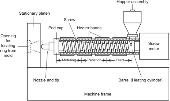
Fig. 6.1 Injection unit configuration.
![1667439773860911.png @J`S5Q}JD3@J[F{{L]GZR(6.png](https://www.atmsh.com/Uploads/image/20221103/1667439773860911.png)
Fig. 6.2 Screw tip configuration.
Another consideration with MIM is the screw configuration. MIM materials are typically shear-sensitive and less compressible than pure polymers, thus the requirement for the screw is different. In general, the screw has three different regions-the feed zone near the hopper, the transition zone, and the metering zone near the screw tip, as shown in Fig. 6.1. The size and depth of these different regions affect how well the material feeds and how much shear is put into the material. In the simplest sense, the compression ratio is the ratio between the flight depth of the feed zone and the metering zone. However, this is true only if the flight width and spacing of the screw geometry and the length of the feed and metering zone are identical. The true compression ratio is the volume ratio of the volume within flights between the feed zone and the metering zone. The higher the compression ratio, the more shear heating and compression the feedstock will experience. The compression ratios used for MIM screws are typically lower than for plastic screws. A typical general purpose thermoplastic compression ratio is 2.3, process sensitive materials such as polyvinyl chloride (PVC) and liquid silicone have compression ratios less than 2.3, and nonsensitive materials may have compression ratios up to 3.0. MIM material compression ratios are typically in the 1.7-2.2 range; however, larger compression ratios have been used and in some cases might be desirable, for example, where materials may have a significant amount of air bubbles as a result of poor mixing, they could be better processed with a higher compression ratio screw and for materials that have less shear sensitivity.
Micro-sized components can be fabricated using both conventional molding machines and those specifically designed for components of this size scale. When using conventional molding machines, the runner and component must make a significant enough shot size to register as a change on the injection unit controller. This can be accomplished by using a larger runner system as compared to the component of interest or by using a small-sized screw. The down-side to the method of using a larger runner is the waste material associated with the larger runner, although this material can be reused. Also, the smaller the screw, the greater the shear rate at the screw tip in order to obtain the same volumetric fill rate as compared to a larger screw. This higher shear rate results in powder/binder separation and subsequent galling at the screw tip.
Also available on the market are machines specifically designed for micromolding.These machines possess a two-stage injection unit. The first stage consists of a screw that feeds material very similarly to a reciprocating screw. In this stage, the material is melted and metered to eliminate any air voids into a plunger or screw configured barrel. The second-stage plunger or screw is used to provide small, very accurately controlled dosages of material into the cavity. The pre-metered material has a more uniform consistency with little air void space, which provides for a more accurate shot size and pressure control during the second-stage injection. These two-stage machines are typically more costly than conventional molding machines. A sketch of a micromolding injection unit configuration is shown in Fig. 6.3. The fabrication of micro components is covered in Chapter 11.
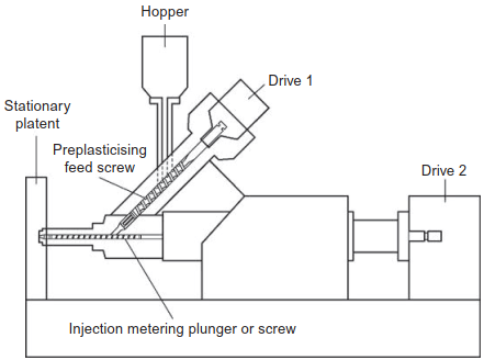
Fig. 6.3 Two-stage microinjection molding injection unit configuration.
The mold is a significant factor in successful injection molding of both plastics and MIM feedstock. The mold performs several key functions. It contains the scaled-up component geometry cavity and melt delivery system, acts as a heat exchaner to remove or add heat to ensure defect-free molding, mates with the injection unit, withstands the clamping and injection forces, and ejects the molded component.
Special care must be taken when designing the mold. The component must be easily ejected to avoid damaging the green components. A significant difference between thermoplastic injection molding and MIM is that the MIM material is very brittle as compared to most thermoplastics, thus, tooling that allows easy ejection of components is essential. The mold must be equipped with a temperature control system that will provide uniform and sufficient temperature to all regions of the part, to ensure even cooling rates, which influences dimensional stability and defect formation. Blisters are a common defect when the mold is unable to sufficiently remove the heat that the molten MIM compound brings to the tool. Mold design is addressed in Chapter 4.
This section gives an overview of the auxiliary equipment used and needed for the injection molding process.
Feedstock with hygroscopic binder systems will require the feedstock to be dried before processing-;particularly if the molding is performed in a high-humidity, nonair-conditioned atmosphere. Typical systems that contain polyethylene glycol (PEG) or polyvinyl alcohol (PVA) would be candidates for drying. The drying can be accomplished using desiccant bed or compressed air dryers. Drying the material helps to eliminate moisture-related defects such as blisters and powder binder separation. Machine metering problems can also be a moisture-related symptom. These problems often show up in the humid time of summer and disappear during the dry winter months.
The mold temperature controller's main function is to maintain a desired mold temperature setting appropriate for the component and feedstock combination being molded. The mold temperature controller circulates cooling fluid through the mold's cooling circuits to provide equilibrium to the heat flux experienced by the mold for every cycle. It is common to run separate mold temperature controllers for each mold half. This set-up allows for greater process control and processability. If a hot sprue is used on the stationary half of the tool to bring the molten MIM feedstock to the parting line, this half of the tool requires a greater amount of cooling, thus having a separate controller here will allow the temperatures of the two mold halves to be more accurately controlled.
Granulators are essentially rotary grinders that are used to grind scrap parts and melt delivery systems (sprues and runners) into feedstock-sized granules for reprocessing. This allows the molder to reduce waste and produce components more cost effectively. Since these granulators will be used to cut polymers that are loaded with metal powders, the wear of the cutting blades is great. As such, the blades should be manufactured from carbide or a tool steel with high wear resistance. A design that allows resharpening of blades is desirable. Many granulators are designed so that the blades must be completely replaced when they are worn. The last consideration with respect to granulators is to have a granulator that is easy to clean thoroughly to avoid cross contamination between MIM materials. Having a granulator to serve each material or molder may be desirable.
Once the part has cured or solidified in the tool, it can be dropped into a container, dropped onto a conveyor, or picked out of the molding machine by a robot or by an operator when the machine uses a semiautomatic cycle. Conveyors can be either continuous and/or indexing. For parts with high green strength, this can be an acceptable form of part removal; however, fragile components or components that require no cosmetic defects such as "dings" or "scuffs" must avoid this technique. Robots are employed when a high level of automation is needed for cost considerations and/or when green strength is low and the parts are susceptible to contact damage. Robots allow for precise placement of the green components into green machining stations and/or sintering fixtures.
The molding process begins once the mold and barrel have reached the molding equilibrium temperature. The reciprocating screw in the heated barrel augurs the required volume of material, or the shot size, to completely fill the gate, runner, sprue, and cavity, yet still maintain a small amount of material in front of the screw for a cushion. The cushion is critical for providing ample material for complete part filling and it accommodates for any feedstock variation. If insufficient cushion is available, the screw will bottom in the barrel resulting in low-mass components, voids, and incomplete cavity fill. Once the shot size is achieved, the mold closes and the screw tip now acts as a plunger via a nonreturn valve or check ring that allows the feedstock to be injected through the nozzle tip of the injection unit, into the sprue, runner, gate, and part geometry of the mold. Other technologies, such as a smear tip (which is a conical device used in place of a nonreturn valve at the discharge end of an injection screw) are available if the metal being molded galls on the check ring and causes binding of the check ring on the barrel, or if the feedstock is particularly susceptible to shear degradation. These are best suited for higher viscosity materials and for small parts where holding pressure is not as critical to fully pack out the mold cavity. The use of a smear tip reduces the available injection pressure and hold pressure since it allows material to flow past, as compared to a conventional check ring and seat configuration.
The time required to fill the mold cavity to 92%-98% full is called the fill or injection forward time. The fill time is controlled by the injection velocity profile set on the machine controller and is dependent upon the viscosity of the melt and the runner and component geometry. This velocity is referred to as the fill rate or fill velocity. The fill rate can be profiled in many different ways and is a bit of an art, as it is strongly influenced by material behavior and tooling configurations. For example, the profile might start slowly during runner filling to prevent gate defects and jetting into the part, followed by a fast injection, and finally slowed down prior to switchover to hold pressure. In other cases, the fill rate is profiled to first inject at a fast velocity to prevent flow lines or wrinkling in the part at the beginning of fill and then the velocity is reduced at the end of fill. Reduction of fill rate prior to completely filling the component is essential to reduce the chance of over-packing the part or causing flash. Flash is the material that escapes through the parting line of the two mold halves or along two pieces of steel in the mold, such as along a slide face or along the interface between ejector pin and its cavity.
Once the cavity is 92%-98% full, the process transfers from a velocity-controlled filling stage to a pressure-controlled stage that finishes filling the last 2%-8% of the cavity and compensates for the volumetric shrinkage that occurs due to the pressurevolume-temperature (PVT) behavior of the feedstock as it cools in the mold cavity. The switchover does not occur at 100% full cavity in order to avoid over-packing the cavity, which often causes flash. The pressure applied during the final filling and compensation stage is commonly referred to as the hold or pack pressure and the duration is referred to as hold or pack time. The hold time is the time in which hold pressure is applied until the gate has frozen and feedstock can no longer be pushed into the part geometry. A gate freeze study (part weight versus hold time) is used to determine the appropriate hold time. This ensures that the gate is frozen, the cavity is completely packed, and no material can escape the mold cavity once the hold pressure is released. Fig. 6.4 shows a typical gate freeze study. In the example shown, the hold pressure needs to be held for 3 s to ensure complete filling of the component and to avoid sink defects.
Upon completion of part filling and packing the part is subject to a cooling time to ensure that the component green strength is adequate to withstand the ejection forces and removal. Concurrent with the cooling time is shot size generation, which is called plastification. During plastification, the screw reciprocates at a set r/min to augur material in front of the check ring. During screw rotation, the material must overcome the backpressure set on the machine controller to push the screw back in the barrel and generate the required shot size. The backpressure generates additional shear heating and ensures a fully compressed feedstock. An increase in back-pressure can be used to remove any voids in the material. If the material is difficult to plastify or feed in the screw, a decrease in backpressure is used. It is very important that the r/min and backpressure are set so plastification is completed 2 s prior to completion of the cooling time to ensure consistent cycle times.
Once the cooling time and plastification are complete the clamp decompresses, the mold opens and the green component is ejected and removed, at which point the process can be repeated. The complete molding cycle is depicted in Fig. 6.5.
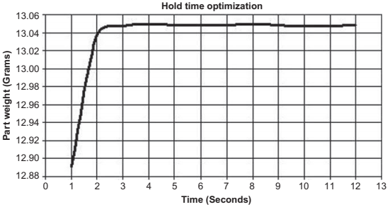
Fig. 6.4 Graphical representation of a typical gate freeze study used to ascertain the optimum pack time. A 3 s hold time would be optimal in this case.
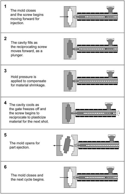
Fig. 6.5 Injection molding process overview
Although there are many parameters in molding and all find importance in particular molding conditions, the most critical molding parameters are mold and melt temperature, injection speed, switchover point and method, hold pressure and time, and cooling time. Note that the following discussion presents generalizations since all these parameters are interrelated, which can convolute troubleshooting and process optimization. For example, an increase in mold temperature can increase the ability to fill a component completely; however, this can be overshadowed by injection speed, switchover pressure, and hold pressure.
Mold and melt temperature
The mold and melt temperature should be set at a temperature that will produce defectfree parts. In other words, these are often changed within a process window to reduce temperature-related defects such as blisters, gate blemishes, short shots, weld lines, etc. The melt temperature is typically 10-20℃ above the melting temperature of the backbone polymer, which is the highest temperature polymer in the compound. If the temperature is set too low, poor flow characteristics like flow lines could be evident. Also, at too low a temperature, the backbone polymer may show as separate strands in the component and leave voids in the final sintered product. This is also evident when the material is compounded at too low a temperature or for too short a time. Low temperature also shows as variability in green part mass and variability in switchover pressure or position depending on the method of switchover. When the temperature is too high, the material will experience more shrinkage in the tool and this may result in cracking. Also, too high a temperature can result in blister defects, flash of the lower melting temperature polymer along the parting line and into the interface between the ejector pin and the cavity block, or problems in the injection unit where the powder/polymer separation can cause the metal to gall onto the check ring of the screw. Furthermore, too high a melt temperature results in degradation of the polymer carrier and can result in short material life.
Mold temperatures influence how well the component can fill and the production of defect-free components. Too low a temperature can cause the component not to fill completely and to have flow defects. Too high a temperature can result in blisters and flashing.
Typical melt temperatures for common wax-polymers systems are 150-190℃ and the mold temperature is 25-55℃. Typical melt temperatures for catalytic systems are 200-260℃ and the mold temperature is 100-150℃.
Injection speed
MIM injection speeds are typically higher than those for polymers because of the higher-thermal conductivity of the feedstock as compared to pure polymers. The injection speed is typically set at the minimum injection speed required to completely fill the component without any defects. Too low an injection speed will result in surface imperfections such as flow lines, poor weld lines, and incomplete fill. Too high an injection speed will result in flash and gate blemishes due to powder/binder separation and potentially voids, if the injection is too fast to allow the air inside the cavity to escape at the mold vents.
Switchover point and method
The ideal injection molding process is one where the component is 98% filled under velocity control and then switched to a pack control for the remaining 2% of component volume. Many studies have been conducted to evaluate different methods of switching from velocity control to pack control during the injection molding operation. The four switchover methods of most importance are position, hydraulic pressure, time, and cavity pressure. Of the four, cavity pressure is the most repeatable. In this technique, a pressure transducer located in the melt stream is used to detect a pressure, which is used to signal the machine to stop velocity control and start pack control. This transducer can be located at the nozzle tip, in the runner, or in the component cavity. The component cavity or runner is the most accurate; however, it is the most expensive since it must be incorporated into each tool, which is an added tooling expense. In general, the closer you are to your actual component cavity, the more accurate your switchover.
Switchover using position is a practical method to obtain consistent production. In this technique, a linear transducer is used to signal that the screw has reached a preselected position. This technique ensures that the screw reaches the same position for each cycle, even if the screw begins to foul. Because of this potential fouling, other safety controls such as screw torque limiting or statistical process control (SPC) of switchover pressure is used to ensure that the screw or screw tip does not become damaged. This type of safety control is also used with the pressure transducer switchover technique.
Time and hydraulic pressure switchover methods should be avoided. Time switchover uses an injection time to switch from speed to pressure control. This method can be variable since the material may have different pressures at switchover due to variability in the feeding behavior of the material. Hydraulic pressure switchover uses the pressure of the hydraulics in the injection unit to switch into pack control fill. This technique can be accurate; however, over long run MIM production, if the check ring becomes fouled, the screw does not reach the same position for the same pressure, and thus the components will begin to lose mass or show defects such as sinks or short shots. Thus, this technique is not recommended for MIM.
Hold pressure and time
Hold pressure and time are important to ensure that the component is completely packed out. Typically, the hold pressure is selected to be approximately the same pressure at switchover, depending on material behavior and tooling configuration. An example to the contrary is a component geometry which may have a feature with a thin section that is difficult to fill, but the thickness of the component is relatively low; in this case a high switchover pressure may be required to obtain fill, but a low hold pressure may be desirable as the part does not need the high pressure to compensate for sink formation because it is a relatively thin component. A gate freeze study is used to determine the hold time. Signs of insufficient hold pressure or time are voids and sinks. Signs of excessive hold pressure or hold time are warpage, gate defects, and flashing. The hold pressure can also be profiled to reduce molded-in stresses that may show up as warpage or cracking in subsequent debinding and sintering.
Cool time
Cool time is important to ensure that components are completely solidified prior to ejection. If the component is cooled for too long or too short a time, the component can be damaged during ejection. Cooling that is too short results in damage such as ejection pin damage on the component or ejection warpage. Cooling that is too long results in cracking of the component during ejection. Short cooling times can be used to remove damage-prone components from the tool when they still have some elasticity as a result of being under-cured. A mold closing delay can also be used for this process step to ensure that the tool cools for the next cycle.
The manipulation of the injection molding process conditions for the MIM process can modify the associated volumetric shrinkage, which subsequently affect the final sintered dimensions. For instance, as melt temperature, mold temperature, and part thickness increase, so does the amount of shrinkage. It is well known that polymers have positive coefficients of thermal expansion and are highly compressible in the molten state. As a result, the volume that a given mass of material occupies will change with both temperature and pressure. Multiple studies have determined that hold pressure has the largest effect on shrinkage in plastics. All studies agreed that increasing hold pressure decreased the amount of shrinkage. Some of the process variable/shrinkage relationships are generalized in Fig. 6.6. These shrinkage characteristics also prove to be true for MIM components.
Accurate linear-shrinkage prediction of MIM components for tool scale-up is commonly achieved by a combination of estimating sintering shrinkage and prototyping or through historical shrinkage data gathering. When a new material is being developed, sintering shrinkage calculations for mold scale-up can underestimate the final sintered shrinkage by up to 2% since it does not consider the shrinkage during molding. Historically, linear shrinkage (YS), as shown in Eq. (6.1), was calculated as a function of the initial solids loading (ϕ) of powder in the feedstock, the theoretical density of the powder (ρt), and the final sintered density (ρ), as described in the following equations.
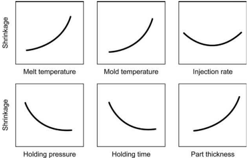
Fig. 6.6 Typical shrinkage relationships with various process parameters.

However, when the sintering shrinkage (YS) is used for mold scale-up (Zs), as shown in Eq. (6.2), components are found to be undersized. Therefore, the engineer must manipulate the tool dimensions, feedstock formulation, and the sintering process to achieve the target dimensions specified by the design engineer.

Inaccuracy of component shrinkage can be corrected by considering the shrinkage associated with the injection molding process as defined by the MIM feedstock's PVT behavior during injection molding of a MIM feedstock. The molding shrinkage can be estimated from the PVT behavior of the molten powder/binder feedstock and combined with sintering shrinkage for accurate shrinkage. The PVT relationships are commonly represented by a two-dimensional diagram as shown in Fig. 6.7. The PVT graph for polymer-behaving systems, like MIM feedstock, normally depicts the specific volume plotted against temperature at various pressure isobars. Essentially, by using these data the injection molding process can be traced on the PVT diagram, if the processing conditions and several key material properties are known. Once the cycle is traced on the PVT diagram it is then possible to predict the volumetric shrinkage due to injection molding (Sv), as shown in Eq. (6.3), of the component by subtracting the specific volume of the component at equilibrium (υe), point 5, from the specific volume of the component at the time of gate freeze (υgf), point 4. Although, specific volume does give an accurate depiction of the volumetric shrinkage in a part, linear shrinkage (SL) is much more useful to the tool engineer.
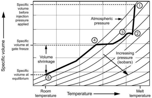
Fig. 6.7 PVT diagram with molding cycle trace. 1. Polymer in barrel at melt temperature, 1-2. Pressure increases as cavity fills, 2-3. Switches to holding phase, 3-4. Pressure decreases as melt solidifies, 4. Gate freezes off, 4-5. Part shrinks until equilibrium is reached. Plastic part design for injection molding. New York, USA: Hanser/ Gardner.

Assuming that the part undergoes isotropic volumetric shrinkage, the linear shrinkage equation is then given by Eq. (6.4)

A PVT diagram for a 63 vol% carbonyl iron wax-polymer MIM feedstock is presented in Fig. 6.8. From this diagram, it is possible to see the different hold pressures and subsequent specific volume associated with these hold pressures. Upon comparison of these data, as obtained from the modified two-domain Tait PVT model, with actual measured volumetric behavior, one can clearly see the correlation of volumetric shrinkage with pack pressure. This is shown in Fig. 6.9. The accuracy of this predicted green shrinkage from the modified two-domain Tait PVT model was within 6.5% error of the experimental results in this particular analysis. Both the green shrinkage and the PVT predicted shrinkage have a slope of -0.0002 (mm3/mm3)/MPa. Thus, the holding pressure during injection molding can significantly affect final molding component dimensions and mass of components, which subsequently influence the final component dimensions.
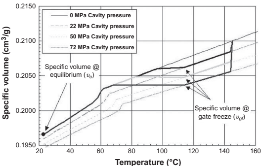
Fig. 6.8 PVT diagram with the injection molding cycle traces for the 30MPa, 60MPa, and 90MPa cycles for a 63 vol% carbonyl iron wax-polymer feedstock.
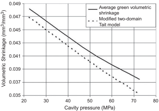
Fig. 6.9 MIM volumetric shrinkage predicted from the PVT behavior of a MIM feedstock compared to the average measured green volumetric shrinkage.
A combination of both sintering shrinkage (Eqs. 6.1, 6.2) and molding shrinkage (Eqs. 6.3, 6.4) is required to obtain accurate shrinkage predictions. The combined linear shrinkage (YC) can then be used to more accurately calculate the combined mold scale-up (ZC) required to account for molding and sintering shrinkage, Eqs. (6.5), (6.6) .

In Fig. 6.10, the theoretical linear sintering shrinkage, as derived from Eq. (6.1), which considers only the shrinkage from sintering, is compared with average measured sintered linear shrinkage and the shrinkage calculated using Eqs. (6.5), (6.6). A significant disparity exists between Eq. (6.1) predicted results and measured sintering shrinkage. This is only corrected when the PVT effect is incorporated into the shrinkage equation. Therefore, shrinkage at molding contributes to the total shrinkage of sintered components. When no PVT effect is considered, the sintered shrinkage as defined by Eq. (6.1) underpredicts dimensions by an average of 0.015mm/mm (1.5%) since it does not account for the effect of cavity pressure on the final shrinkage of the sintered components.
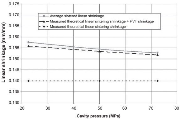
Fig. 6.10 Comparison of measured sintering shrinkage with the shrinkage predicted from sintering and sintering plus the PVT shrinkage.
The melt history in injection molding of both MIM and thermoplastics can be quite complex and can result in anisotropic shrinkage. The material is also affected by orientation during injection, multiple pressures during the injection process, part geometry, flow patterns, time, and cooling rates. All these factors may lead to anisotropic shrinkage. Fig. 6.11 shows a MIM component molded with a 63% solids loading carbonyl iron wax polymer feedstock that was characterized for anisotropic behavior. The dimensions characterized were the thickness at gate (denoted "Thickness gate"), thickness at end of fill ("Thickness EOF"), width at gate ("Width gate"), width at end of fill ("Width EOF"), and length ("Length"). After molding, these component dimensions were measured and compared to the tooling to characterize shrinkage, as shown in Fig. 6.12. Interestingly, the thickness of the component experiences the greatest shrinkage. Logically, of the two thickness measurements, the gate area experiences the least amount of shrinkage since the holding pressure would be greatest in this region. The reason for the greater shrinkage in the thickness direction is attributed to internal stresses created within the component as the polymer component of the feedstock freezes off in layers. The layers create a mechanical coupling within the solidifying and shrinking component.
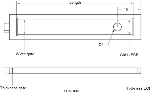
Fig. 6.11 Labels used to describe features measured for anisotropic shrinkage analysis
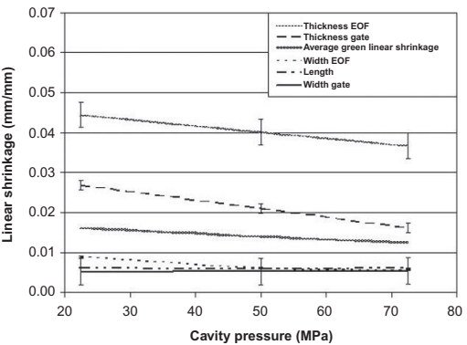
Fig. 6.12 Measured experimental green anisotropic shrinkage
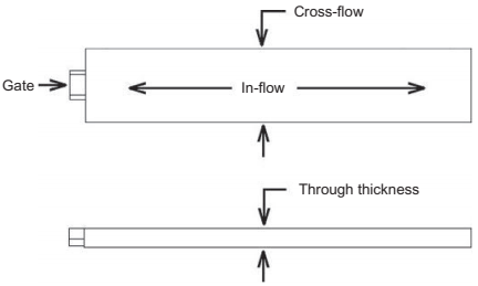
Fig. 6.13 Description of flow direction terminology
Fig. 6.13 illustrates the cross-flow direction, in-flow direction, and through-thickness direction of flow. The layers exhibit a strong interlocking force in the cross-flow and in-flow directions (Fig. 6.14). Therefore, the largest amount of volumetric shrinkage is achieved through the thickness of the component. Explain that the outer layers crystallize at higher pressures. However, component is crystallizing at lower pressures, therefore, more volumetric shrinkage occurs.
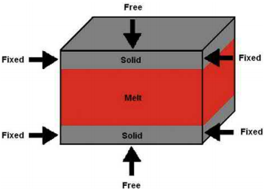
Fig. 6.14 Description of mechanical coupling. The through-thickness direction is free to shrink. The in-flow and cross-flow directions are constrained due to internal stresses and mechanical coupling.
Anisotropic shrinkage in MIM and in standard injection molded polymer materials is a very common phenomenon. However, there are many factors that influence the shrinkage anisotropy. For semicrystalline materials, cooling rate, polymer, and/or filler orientation in the direction of flow during crystallization, mold restraints, internal stresses, and pressure gradients also affect the magnitude and direction of the shrinkage.
Anisotropic shrinkage makes tool scale-up extremely difficult. The most common practices for avoiding nonuniform stress distributions caused by anisotropic shrinkage include uniform cooling of all cavity and core components, utilizing a decreasing hold pressure profile to ensure even packing, and the use of mold filling and packing simulation software to optimize the process.
Injection molding defects in the MIM process can be apparent directly after molding or they may not manifest themselves until after subsequent process steps. Molding is a multivariable process where the variables are heavily interactive, thus, there are multiple ways to solve a problem. Also, the solution to one issue can cause defects of a different form. Table 6.1 is a guide to common defects and potential solutions.
Table 6.1 Common defects and solutions for MIM molding
Defect | Potential causes | Potential solution |
Blistering | Improperly dried material | Dry hygroscopic material Reduce humidity in plant |
Blistering | Poor heat removal from tool | Increase cycle time Reduce mold temperature Reduce melt temperature More cooling channels in tool Higher-thermal conductivity mold components |
Blistering | Localized shear heating | Reduce injection speed Larger gates to reduce shear heating |
Blistering | Polymer degradation | Use higher MW polymers Use antioxidant in binder |
Cracking | Ejection issue | Increase mold temperature Reduce pack pressure Decrease melt temperature Polish tool Decrease cool time |
Cracking after solvent | Molded in stress | Increase venting Increase mold temperature Post mold anneal Decrease pack pressure |
Flash | Tooling not closed | Adjust tooling for better clamping Worn tooling, dress parting line Clean mold faces of dirt |
Flash | Too low clamp tonnage | Higher tonnage machine Reduce injection pressure by slowing injection Reduce pack pressure |
Flash | Material viscosity | Increase viscosity by increasing solids loading (will cause shrinkage change) Increase viscosity by high molecular weight polymers |
Gate blemish | Powder/binder separation at gate | Decrease injection speed Decrease pack pressure |
Incomplete fill | Insufficient material in cavity prior to gate freeze | Increase shot size and cushion Increase pack pressure Increase injection speed Increase venting Increase melt temperature Increase mold temperature |
Incomplete fill | Material feeding issue | Decrease backpressure on recovery Decrease size of feedstock granuals Dry material for hygroscopic material Decrease fines in feedstock |
Sinks | Poorly filled part | Increase pack pressure or pack time Increase gate size Increase backpressure for screw recovery Decrease melt temperature to decrease material shrinkage Increase melt temperature to allow greater fill Increase venting Increase cushion |
Variable component Mass | Shot size variation | Clean check ring Increase recovery backpressure Increase cushion |
Voids | Air entrapment | Decrease injection speed Increase backpressure during recovery Increase pack pressure and time |
Warpage | Component distorts during ejection | Increase cool time Decrease mold temperature Better cooling in tool |
Warpage | Pressure gradient in component | Decrease hold pressure |
Weld lines | Premature material solidification | Increase injection speed Increase melt temperature Increase pressure for switchover to pack control |
Weld lines | Gas entrapment in mold | Increase venting on part and runner Decrease injection speed |
Wrinkles | Premature material solidification | Increase injection speed Increase melt temperature |
Contact: Cindy Wang
Phone: +86 19916725892
Tel: 0512-55128901
Email: [email protected]
Add: No.6 Huxiang Road, Kunshan development Zone, JiangsuShanghai Branch: No. 398 Guiyang Rd, Yangpu District, Shanghai, China