Powder-binder formulation and compound manufacture in metal injection molding (MIM
Table of Contents
4.1 Introduction: The role of binders
Binders play a very crucial role in fabricating components by metal injection molding (MIM). Binders are multicomponent mixtures of several polymers. A binder typically consists of a primary component to which various additives like dispersants, stabilizers, and plasticizers are added. The basic purpose of binders is to assist in shaping of the component during injection molding and to provide strength to the shaped component. Binders act as a medium for shaping and holding the metal particles together until the onset of sintering. The binders are mixed with metal powders to make feedstocks, which are further used as starting materials for injection molding. Binders are removed after molding prior to sintering of the component.
Binders have an influence on metal particle distribution, shaping process, dimensions of the shaped component, and final properties of the sintered component. The important characteristics required in binders are summarized in Table 4.1. The binder should have a low contact angle with metal particles. The low contact angle will result in better wetting of binder to the powder surface, which will assist the mixing and molding process. The binder and the metal particles should be inert with respect to each other. The binder should not react with metal particles and in turn the metal particles should not polymerize or degrade the binders. The binder powder mixture (feedstock) should satisfy various rheological requirements for successful molding of the components without formation of any defects. The viscosity of the feedstock should be in an ideal range for successful molding. Viscosity that is too low during the molding process will result in separation of powders and binders. On the other hand, viscosity that is too high will impair the mixing and molding process. Apart from the requirement of an ideal viscosity range during the molding process, the feedstock should also have the characteristic of a large increase in viscosity on cooling. The large increase in viscosity will assist in preserving the shape of the compact on cooling.
Table 4.1 Characteristics of an ideal binder system for metal injection molding process
| | Desirable characteristic |
Powder interaction
Flow characteristics
Debinding
Manufacturing
| Low contact angle Good adhesion with powder Capillary attraction of particles Chemically passive with respect to powder Low viscosity at the molding temperature Low viscosity change during molding Increase in viscosity on cooling Small molecule to fit between particles Degradation temperature above molding and mixing temperatures Multiple components with progressive decomposition Temperatures and variable properties Low residual carbon content after burnout Noncorrosive and nontoxic burnout products Easily available and inexpensive Long shelf life Safe and environmentally acceptable Not degraded due to cyclic heating High strength and stiffness Low thermal expansion coefficient Soluble in common solvents High lubricity Short chain length and no orientation |
The binder should possess the characteristic of fast removal during debinding, without forming defects in the injection molded component. The green part is most susceptible to formation of defects during the debinding stage. The binder, which provides strength, is removed, gradually increasing the susceptibility of the green part to formation of defects. The absence of open porosity during the initial stages of thermal debinding results in the formation of defects such as cracking, blistering, etc. The stresses arising owing to trapped degradation products as a result of polymer burnout will lead to the formation of defects. To avoid this scenario, the binders are typically designed to have multiple components which undergo decomposition at different temperatures. In this case, the debinding process occurs in two stages. In the first stage, one component of the binder system is removed, initially resulting in creation of open pores in the green component. During this stage, the remaining components of the binder system will provide strength to the metal particles and retain the shape. The remaining components of the binder system are gradually removed during the second stage of the debinding process. The two-stage debinding process results in faster removal of binders from the green components. The binder should also possess the characteristic of complete burnout without leaving any residual carbon. The products formed due to thermal debinding should also be noncorrosive to the manufacturing equipment.
Binders used for MIM must be easily available, low in cost, and should have a long shelf life. The sprues and gates are reused in the MIM process and the binder should have good recyclability and must not degrade on cyclic reheating. The binders should have high thermal conductivity and a low coefficient of thermal expansion in order to prevent defects formed as a result of thermal stresses.
It is very hard for a single binder to fulfill all the characteristics of feedstock. The binder system used in the injection molding process typically contains multiple components, each performing a specialized task. The binder system contains a major constituent and other components are mixed as additives to obtain the desired characteristics of the feedstock.
4.2 Binder chemistry and constituents
4.2.1 Binder chemistry
Polymers can be classified as thermoplastic and thermosetting materials based on their chemistries and reversibility of phase change. Thermoplastic polymers are formed due to repetition of small monomer groups along the chain length without cross linking. Polyethylene, polypropylene, polystyrene, and wax are some examples of thermoplastic polymers. The crystalline polymers have smaller chain lengths and amorphous polymers contain longer chain lengths. The amorphous polymers are more ductile in nature than crystalline polymers. The crystalline and amorphous polymers show different behaviors on exposure to high temperature (Fig. 4.1). Polymers with relative mass lower than M1 will display a narrow melting point, which will result in shape loss during the debinding process. Polymers with relative mass greater than M2 will require a high temperature to become viscous. The high temperature will cause degradation of the polymer. Thus, ideally, the relative mass of the polymer to be used as a binder should fall between M1 and M2 .
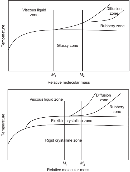
Fig. 4.1 Temperature in relation to relative molecular mass plots for amorphous (top) and crystalline (bottom) polymers.
Polymers soften and become viscous above a temperature called the glass transition temperature (Tg). The polymers are brittle below the glass transition temperature. Various properties such as volume, thermal expansion coefficient, and enthalpy undergo major changes near the glass transition temperature. The melting point and tensile strength of the polymer depends on the molecular weight, i.e., the chain length of the polymer. The variation of this parameter with molecular weight of the polymer is shown in Fig. 4.2. The viscosity (η) of the polymer also depends on the molecular weight (M) as per the following relation
η = κMα
where κ and α are constants. The value of α is very close to unity for the polymers used n the MIM process
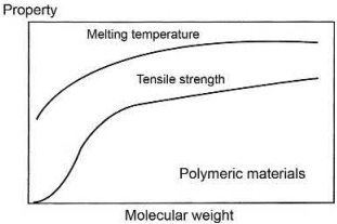
Fig. 4.2 Variation of melting temperature and tensile strength with molecular weight of polymers
Small chain polymers are preferred for use in MIM because of their low molecular weight. Waxes are widely used also because of their low molecular weight, thermoplastic nature, and low melting temperature. Waxes are naturally occurring ester compounds obtained from a long-chain alcohol and carboxylic acid. Some examples of waxes are paraffin wax, beeswax, and carnauba wax. The melting point of all three waxes is lower than 100°C.
Thermosetting polymers undergo cross-linking of polymer units at high temperatures. The cross-linking will result in the formation of a three-dimensional rigid structure. The rigid structure, once formed, is not reversed on reheating. The thermosetting polymer directly vaporizes on heating without melting or softening. As the thermosetting polymers do not undergo melting, the shape loss due to softening of the polymer during debinding can be avoided by using thermosetting polymers. The cross-linking of the thermosetting polymer upon heating can provide strength to the part during the debinding process. The increase in strength on debinding can be useful in retaining the shape of the component. However, thermosetting polymers are rarely used in MIM. The formation of an irreversible rigid structure on heating will prevent recycling of sprues and gates from MIM. It is very difficult to burn out the thermosetting polymers completely during thermal debinding. Some residual amount of carbon is left in the components. Thus thermosetting polymers are used when there is a requirement for residual carbon during the sintering process.
4.2.2 Binder constituents
Dispersants, plasticizers, stabilizers and intermolecular lubricants are some common additives added to binders in the MIM process. Dispersants are added to the binder to enhance the distribution of the powder in the system. Dispersants have the unique ability to replace the powder/powder and powder/air interfaces with a powder/binder interface. The addition of dispersants enhances the solids loading (Mutsuddy, 1994). The dispersants create locations for the binder to react and bond with the powder. Zinc stearate is a commonly used dispersant in the MIM process.
Lubricants enhance the flow of the feedstock. Lubricants have a much lower molecular weight than the polymer and thus possess very much lower viscosity than the base polymer at the processing temperature. Lubricants decrease the friction between the adsorbed layer on the particles and the binder molecules. Stearic acid, wax E, wax OP, etc., are some common examples of lubricants.
4.3 Binder and powder properties and their effects on feedstock
Manufacturing defect-free MIM parts often poses as a challenge to design and process engineers. Additionally, compositional changes in feedstock loading often require the measurement of material properties such as physical, thermal, rheological, mechanical and pressure-volume-temperature (PVT) parameters for performing MIM simulations or related experiments. The following sections address how feedstock properties can be estimated as a function of feedstock composition using a combination of experimental data and semiempirical models. Additionally, the sections discuss how each feedstock property can affect the overall injection molding behavior and part quality. Subsequently, challenges in binder removal and the defects observed in debinding are presented.
4.3.1 Flow: Rheology as a function of shear rate, temperature, and particle attributes
The rheological characteristics, especially the viscosity of the feedstock, play a critical role while filling the mold during the injection molding process. The viscosity of the feedstock increases with addition of metal particles. The feedstocks require shear stress to exceed yield stress to initiate a viscous flow (Bingham systems). Capillary and torque rheometers are used to measure the rheological characteristics of the feedstocks. In capillary rheometers, the feedstock is forced through a small gap and the pressure drop and flow rate are measured. The torque rheometer measures the torque required for mixing the feedstock as a function of time. The capillary rheometer is preferred and widely used for characterizing the feedstocks as the test conditions (shear rates, viscosity) closely match the conditions experienced by feedstocks in the MIM process. The flow of the feedstock through the capillary rheometer is similar to the feedstock filling the mold cavity during the MIM process.
The relative viscosity, which is defined as the viscosity of the feedstock in relation to the viscosity of the binder, increases with the addition of metal particles. The relative viscosity becomes infinity when the addition of metal particles reaches a critical limit. At the limit, the feedstock becomes stiff and does not flow. The amount of metal particles in the feedstock at this limit is called the critical solids loading. In case of mono-sized spheres, the limiting loading occurs at 63.7% solids. The effect of solids loading in the form of randomly distributed spherical mono-sized spheres on the viscosity of liquid was estimated by Einstein according to the following equation:
ηr = 1+2.5ϕ
where ηr is the relative viscosity and ϕ is the solids loading. The equation developed by Einstein can be used for solids loading of less than approximately 15%. Various modeling studies have been further carried out to estimate the variation of relative viscosity with solids loading. Some of the equations developed from these studies are shown as follows:
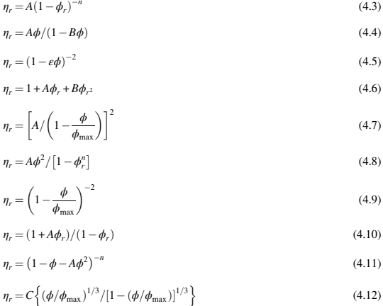
where η is mixture viscosity, ηr is relative viscosity, ϕ is solid volume fraction, ϕmax is maximum solid volume fraction, ϕr is relative solids loading (ϕ/ϕmax), and A, B, and n are constants.
The models developed for estimating the relative viscosity of feedstocks must satisfy certain conditions. The relative viscosity of the only binder should be equal to 1. The first derivative of viscosity must be equal to 2.5 for zero volume fraction and the relative viscosity should be infinity at the maximum solids loading.

The most suitable model based on experimental studies to estimate the change in relative viscosity with relative solids loading is listed in Eq. (4.16)

where ηr is the relative viscosity and ϕr is the relative solids loading. The exponent n is found to be equal to 2.0 and the coefficient A is typically near unity. The relative viscosity variations for various systems as shown by Eq. (4.16) are shown in Fig. 4.3.
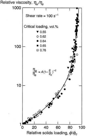
Fig. 4.3 Variation of relative viscosity with solids loading estimated from Eq. (4.16)
Effect of shear rate
The viscosity of the MIM feedstock is very sensitive to the shear rate. At lower shear rates the feedstocks show a yield point which corresponds to a very high viscosity. As the stresses exceed the yield point, the viscosity of the feedstocks decreases with further increase in shear rate. At higher shear rates, the particles increase in volume (dilate) as they slide past one another, resulting in an increase in viscosity. The shear dilation is absent at low solids loading due to the high amount of liquid and little ordering of particles. The polydisperse systems exhibit a gradual change in viscosity with shear rate when compared to mono-sized systems. The dilation process is also absent in case of polydisperse systems. The surface active agents lower the viscosity of the feedstock but have no effect on the shape of the viscosity versus shear rate curves.
The Cross-WLF model can be used to model the viscosity dependence of any given powder-polymer mixture on shear rate as shown in Eq. (4.17).

where η is the melt viscosity (Pa s), η0 is the zero shear viscosity, γ is the shear rate (1/s), τ* is the critical stress level at the transition to shear thinning, determined by curve fitting, and n is the power law index in the high shear rate regime, also determined by curve fitting.
Effect of temperature
The viscosity of the feedstock decreases with the increase in temperature. The decrease in viscosity with increase in temperature will be greater for the feedstock than in the case of pure binder. The larger decrease in viscosity in the feedstocks is primarily due to the combined effect of the decrease in viscosity of binder and change in volume fraction of the solids as a result of difference in thermal expansion coefficients. The lower viscosity of the feedstock at higher temperature can be utilized to increase the solids loading during the injection molding process. The mixing of the feedstocks is also easy because of the lower viscosities at high temperature. However, molding the feedstock at higher temperatures will result in an increased processing time due to longer times required for cooling and also causes defects in the molded samples due to larger contraction of binder on cooling from the higher processing temperature.

The temperature dependence of viscosity of any powder-polymer mixture can be calculated using Eq. (4.18).
where T is the temperature (K). T*, D1 and A1, are curve fitted coefficients. Additionally, A2 is the WLF constant and is assumed to be 51.6 K. The values of these coefficients can be obtained by curve-fitting the estimated viscosity for different volume fractions of powder at various shear rates and temperatures and examples are summarized in Table 4.2.
Material |
| Density (g/cm3) | Specific heat, (J/g-℃) | Thermal Conductivity (W/(mK)) | Coefficient of thermal expansion 1026/K | Elastic modulus (GPa) |
Wax-polymer |
| 0.88 | 3.16 | 0.19 | - | 2.56 |
Aluminum | AI | 2.7 | 0.900 | 180 | 23 | 70 |
Copper Cu | Cu | 8.75 | 0.385(0-100℃) | 360 | 13 | 130 |
Invar | Fe-36Ni | 8 | 0.515 | 20 | 5 | 205 |
Kovar or F15 | Fe-29Ni-17Co | 7.7 | - | 17 | 4.9 | 200 |
Molybdenum-copper | Mo-15Cu | 10 | - | 170 | 7 | 280 |
Molybdenum-copper | Mo-20Cu | 9.9 | - | 145 | 6.5 | 280 |
Tungsten-copper | W-10Cu | 17 | 0.160(0-100℃) | 209 | 6 | 340 |
Tungsten-copper | W-20Cu | 16 | - | 247 | 7 | 290 |
Tungsten-copper | W-30Cu | 14 | - | 260 | 11 | 260 |
Cobalt-chromium or F75 | Co-28Cr-4W-3Ni-1C | 8.80 | - | 14.7 | 12.8 (20-100℃) | 235 |
Hastelloy x(HT) | Ni-22Cr-18.5Fe-9Mo-1.5Co-0.6W | 5.20 | 0.427 | 7.20 at 168℃ | 11.2 (24-93℃) | 205 |
Inconel 718(HIP, HT) | Ni-19Cr-18Fe-5Nb-3Mo-1Ti-0.4Al | 8.23 | - | 11.4 At room temp | 12.8 (25-100℃) | 200 |
Maragingsteel (HT) | Fe-18Ni-9Co-5Mo-0.5Ti-0.1Si | 8.10 | - | 14.2 At room temp | 11.3 (25℃-100℃) | 190 |
Stainless 17-4pH (HT) | Fe-16Cr-4Ni-4Cu-0.3Nb-0.8Si | 7.81 | 0.460 at 20℃ | 14 At room temp | 10.8 (25-100℃) | 190 |
Stainless 304L | Fe-18Cr-8Ni | 8.00 | 0.500 | 16.3 At room temp | - | 190 |
Stainless 316L | Fe-17Cr-12Ni-2Mo-2Mn | 8.01 | 0.500 (0-100℃) | 5.9 At room temp | 17 | 190 |
Stainless 410(HT) | Fe-11Cr-0.5C | 7.86 | 0.460 | 24.9 At room temp | 9.90 | 190 |
Stainless 420(HT) | Fe-13Cr-1Mn-1Si | 7.86 | 0.460 | 24.9 | 12.2 | 190 |
Stainless440C (HT) | Fe-17Cr-1Mn-1C | 7.86 | 0.460 | 25 | 10.2 | 200 |
Steel 1060 | Fe-0.6C | 7.86 | 0.502 | 49.8 | 11 | 200 |
Steel 4140(HT) | Fe-1Cr-0.4C | 7.85 | 0.473 | 42.6 At 100℃ | 12.2 | 190 |
Steel 4340(HT) | Fe-2Cr-1Ni-1Mn-0.4C | 7.85 | 0.475 | 44.5 | 12.3 at 20℃ | 205 |
Titanium | Ti | 4.51 | 0.528 | 17.0 | 8.90 at 20-100℃ | 116 |
Titanium-5-2.5 | Ti-5Al-2.5Fe | 4.45 | 0.529 | 17 | 11.9 | 112 |
Titanium-6-4 | Ti-6Al-4V | 4.51 | 0.5263 | 6.70 | 8.60 | 113.8 |
Tool steel M2(HT) | Fe-6W-5Mo-4Cr-2V-1C | 8.14 | 0.418 | 22 | 11.5 | 207 |
Tungsten heavy alloy | W-5Ni-2Cu | 17.9 | - | 23 | 5.40 | 276 |
Tungsten heavy alloy | W-4Ni-1Fe | 17.9 | - | 26 | 4.60 | 345 |
Tungsten heavy alloy | W-5Ni-2Fe | 17.494 | - | 20 | 4.62 | 324 |
Effect of particle characteristics
The viscosity of the feedstocks increases with decrease in particle size of the metal particles. The smaller-sized metal particles have high surface area and interparticle friction and these characteristics result in higher viscosity of the feedstocks. The powders having high packing density require a lower amount of binder to attain the viscosity required for molding. The solids loading can be increased significantly with a good packing powder. Powders with a larger difference in particle size can be tailored to improve the packing density and decrease the viscosity of the feedstock for any given fixed solids loading. The change in relative viscosity with the composition (% of small particles) for a bimodal mixture of spheres at a solids loading of 55% and a particle size rate of 21 is shown in Fig. 4.4. The relative viscosity decreases initially reaching a minimum point prior to increasing again with continued addition of smaller size particles.
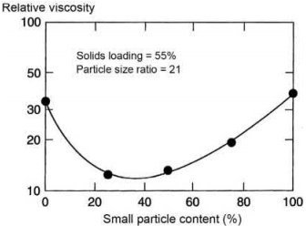
Fig. 4.4 Variation of relative viscosity with % small particle content at solids loading of 55% and particle size ratio of 21
The shape of the metal particles has a significant effect on the relative viscosity of the feedstock. Irregular shaped powders due to high interparticle friction and low packing density result in feedstocks with high viscosities. The small-sized spherical powders are ideal for injection molding because of their better flowability and low interparticle friction. The critical solids loading decreases as the particle size becomes more nonspherical. The spherical powder has the largest critical solids loading. The agglomeration of the powders also results in increase in the viscosity of the feedstock. The increase in viscosity becomes larger with the agglomerate size and with the number of particles in the agglomerate. The variation of relative viscosity with particle shape is shown in Fig. 4.5.
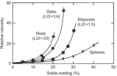
Fig. 4.5 The effect of particle shape on the relative viscosity with increase in solids loading
4.3.2 Solidification: Thermal conductivity, heat capacity
During injection molding, the component after shaping is cooled in the die under external pressure. The pressure is removed once the compact has cooled completely. The difference in thermal properties of the binder and the metal powders results in development of internal stresses in the compact during the cooling stage. These stresses result in distortion of the compact once it is ejected from the mold. The feedstock should have the characteristic of large increase in viscosity on cooling to avoid distortion of the compacts during cooling and subsequent handling. The rule of mixtures provides a very good estimate of the thermal properties of the feedstock. The thermal properties of the feedstock estimated according to the rule of mixtures are given in Eq. (4.19)

where Af is the property of the feedstock, Ab is the property of the pure binder, Am is theproperty of the metal, and ϕ is the solids loading.
The feedstock should possess high thermal conductivity to minimize the formationof shrinkage cracks. The thermal conductivity values of the feedstocks lie in betweenpure binder and metal particles. The thermal conductivity of the feedstock (kf) can beestimated as

where kb is the thermal conductivity of binder, A and B are constants, ϕ is solids loading. Table 4.3 provides the binder thermal conductivity for a waxpolymer binder system and typical metal powders used in MIM. For new feedstock development, feedstock thermal conductivities can be estimated by using Eq. (4.20) along with binder and metal powder thermal conductivity from Table 4.3 for any feedstock solids loading. The heat capacity of the feedstock can be estimated from the modified rule of mixtures (Table 4.4).

where Cpf is feedstock specific heat, Cpb is binder specific heat, Cpp is metal powder specific heat, A is a constant taken as 0.2 for spherical powders, and Xb and Xp are binder and metal powder mass fraction. Table 4.2 provides the binder specific heat for a wax-polymer and a polyacetal binder system and typical metal powders used in MIM. For new feedstock development, feedstock specific heats can be estimated by using Eq. (4.19) along with binder and metal powder specific heat from Table 4.2 for any feedstock solids loading. The variation of heat capacity of various metal feedstocks with the addition of metal powders in different binders is shown in Fig. 4.6. The estimation based on modified rule of mixtures shows a very good agreement with the measured values of the heat capacity of the feedstock.
Table 4.3 Literature cross WLF constants for a waxpolymer binder used in MIM
Cross WLF constants | Wax- polymer binder |
n τ (Pa) D1 (Pa s) T* (K) A1 A2 (K) | 0.4 793.46 4.29E+23 333 78.13 51.6 |
Table 4.4 Literature thermal properties for a wax-polymer binder used in MIM
Temperature(K) | Specific heat Cp(J/kg-K) | Temperature(K) | Thermal conductivity(W/m-K) |
283 298 331 374 423 | 2080 3360 4640 3490 2530 | 316 356 377 397 436 | 0.195 0.182 0.176 0.171 0.162 |
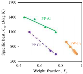
Fig. 4.6 Feedstock specific heat as a function of filler content for various metal powder binder systems
4.3.3 Shrinkage and warpage: Density, PVT parameters, and modulus
In MIM, part quality such as part mass, shrinkage, and warpage are influenced by density, PVT parameters (specific volume as a function of temperature and pressure) and modulus of the feedstock, respectively. The models presented later help predict density, specific volume, and modulus of the feedstock as a function of composition.
Density
The difference in density of the binder and the metal powders correlates with the densities of the molded part and the effective part weight can be determined by multiplying the mold cavity volume with feedstock density. Additionally, the density changesas a function of solids loading in the feedstock and the feedstock density (ρf) can be estimated using the inverse rule of mixtures as

where ρfis feedstock density, ρb is binder density, ρpis metal powder density, Xb and Xp are binder and metal powder mass fraction. Table 4.2 Provides binder density for wax– polymer binder system and metal powder densities for typical metals used in MIM. For new feedstock development, feedstock densities can be estimated by using Eq. (4.22) along with binder and metal powder densities from Table 4.2 for any feedstock solids loading to gauge the expected part mass for a given mold cavity and determine the shot size for injection molding.
PVT parameters
Equation of state (PVT) parameters help in prediciting the amount of shrinkage at a given pressure-temperature combination in injection molding. Specific volume is the inverse of density and feedstock specific volume can be estimated by using a simple rule of mixtures as follows:

where νf is feedstock specific volume, νb is binder specific volume, νp is metal powder specific volume, andXb and Xp are binder and metal powder mass fraction. Table 4.2 provides the specific volume for typical metal powders used in MIM and binder specific volume for a wax-polymer and a polyacetal binder system. For estimating specific volume at a given pressure-temperature combination, a dual domain Tait equation can be used as shown here (Table 4.5)

where υ(T,p) is the specific volume at a given temperature and pressure, υo is the specific volume at zero gauge pressure, T is temperature in K, p is pressure in Pa, and C is a constant assumed as 0.0894. The parameter B accounts for the pressure sensitivity of the material and is separately defined for the solid and melt regions. For the upper bound when T>Tt (volumetric transition temperature), B is given by Eq. (4.25) and b1m, b2m, b3m, b4m, and b5 are curve-fitted coefficients. For the lower bound, when T<Tt, the parameter, B, is given by Eq. (4.26) and b1s, b2s, b3s, b4s, b5, b7, b8, and b9 are curve-fitted coefficients. Eq. (4.27) can give the dependence of the volumetric transition temperature Tt on pressure. The feedstock specific volume can be estimated by using Eqs (4.23)–(4.27) along with binder and metal powder specific volume from Tables 4.2 and 4.3, respectively, for any feedstock solids loading at a given temperature pressure combination.
Table 4.5 Literature dual-domain Tait constants for a wax-polymer binder used in MIM (Kate et al., 2014)
Dual-domain Tait constants | Wax-polymer binder |
b5 (K) b6 (K/Pa) b1m (m3/kg) b2m (m3/kgK) b3m (Pa) b3m (K-1) b1s (m3/kg) b2s (m3/kg K) b3s (Pa) b4m (K-1) b7 (m3/kg) b8 (K-1) b9 (K-1) | 336.15 1.47E-07 1.26E-03 1.34E-06 1.26E + 08 5.87E-03 1.17E-03 8.57E-07 2.40E + 08 4.16E-03 8.46E-05 6.69E-02 1.39E-08 |
Modulus
The difference in elastic modulus of the binder and the metal powders correlates with the modulus of the molded part and the effective part warpage can be determined.Additionally, the modulus changes as a function of solids loading in the feedstock and the feedstock elastic modulus can be estimated using a rule of mixtures as

where Ef is feedstock modulus, Eb is binder modulus, Ep is metal powder modulus, Xb and Xp are binder and metal powder mass fractions. Table 4.2 provides the binder modulus for wax-polymer binder system and metal powder densities for typical metals used in MIM. The feedstock modulus can be estimated by using Eq. (4.22) along with binder and metal powder modulus from Table 4.2 for any feedstock solids loading to gauge the expected part warpage considering feedstock behaves isotropically.


