3.3.1 Pycnometer density (MPIF 63, ASTM D 2638, ASTM D 4892)
3.3.2 Apparent density (MPIF 28 and 48, ASTM B 417 and B 703, ISO 3923-1 and 3953)
3.3.4 Particle size distribution (ASTM B 822-10, ISO 13320-1)
Metal powders that can be manufactured to a sufficiently small size (<45μm), loaded sufficiently into a polymeric carrier, and sintered to a sufficiently high density can be utilized for metal injection molding (MIM). Powder that is <22μm average particl size is optimal. These powders can be produced using various methods; however, the different methods produce different powder characteristics that influence the final components in density, dimensions, distortion, etc. These powders are characterized using methods for small particles, thus, many characterizing methods such as screen analysis are not sufficiently accurate to monitor and predict the MIM process outcomes. This chapter is devoted to MIM powders, the different methods of powder fabrication, the characterization of MIM powders, and the subsequent effects of powder geometry or manufacturing method on the MIM process.
Many metal powders are suitable for MIM provided they are sufficiently small, sinterable, and do not exhibit strong sintering behavior at temperatures where binders are being removed. Magnesium and aluminum are not typical for MIM because of their low-melting temperature and strong oxides, which interfere with sintering; however, aluminum has successfully been MIMed with limited commercial success. More typical MIM alloys consist of stainless steels, low-alloy steels, tool steels, copper and its alloys, titanium and its alloys, soft magnetic alloys, refractory metals both in their pure state and as heavy alloys, and finally cemented carbides. The powders for these metals and alloys are either gas-atomized, wateratomized, or based on elemental mixtures of chemically or mechanically produced powders. Other powder fabrication techniques such as plasma atomization for reactive metals and electrolytic for chromium can be used to produce MIM grade powders, but are less commonly seen.
The ideal MIM powder characteristics are as follows:
<22μm D90 particle size for most alloys, i.e., the stainless, low-alloy steels, etc.; the powders for the refractory metals and cemented carbides are typically <5μm D90;
high packing density in order to load the most powder into polymer as practically possible;
high surface purity to maintain uniform interaction with polymers and promote sintering;
deagglomerated in the case of refractory metals and other chemically produced particles; l spherical particle shape; however, many powders that are not spherical are used for MIM—these powders typically have lower solids loading and subsequently show greater shrinkage since they cannot be loaded at high levels into binder systems;
sufficient interparticle friction to maintain shape during debinding; the number of particleto-particle contacts per unit volume decreases as the particle size increases, thus, larger particles can experience greater distortion;
void-free nonspongy particles to promote good sintered density and product integrity;
minimum explosivity and toxicity; the finer the particle, the greater the surface area, and the greater the possibility for explosion—this is particularly true for titanium, aluminum, and zirconium powders.
Deviations from these ideal characteristics do occur. For example, powder alloying additions in elementally blended mixtures can deviate because of material availability. These nonideal minor additions can result in retardation of sintering densification response but may still provide sufficient final properties.
Small particles are desirable to allow sinter densification of MIM components. Typically, average particle sizes <22μm are used. MIM components made from refractory metals and tungsten carbide hard metal powders start with particles that are typically <5μm in size. The finer particles of these metals and cermets (WC) are a result of the manufacturing method—they have too high a melting temperature to be atomized. WC powders are produced using carburization methods and refractory metals are produced using chemical precipitation or reduction methods.
If smaller features or better surface finish are desired, a smaller particle size such as a 5 μm or 10 μm D90 should be used. The effect of particle size on surface finish is illustrated in Fig. 3.1 for a 17-4PHSS material that was fabricated from both gas-atomized and master alloy technique (alloying techniques are discussed later in this chapter). In this set of observations, a 5-μm powder size showed a better surface finish for both the prealloyed and master alloyed technique. A slightly better surface finish was obtained for gas-atomized materials as compared to master alloyed material. The alloy homogenization that takes place during the sintering of the master alloyed material may have caused the slightly greater surface roughness.
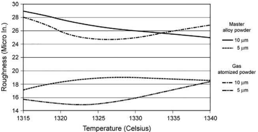
Fig. 3.1 The effect of particle size on surface finish for a 17-4PHSS alloy that was fabricated using both gas-atomized and master alloy techniques.
If cost is a consideration, a larger particle (>30μm) can be used; however, the larger particle size can result in process difficulties such as injection unit screw seizure owing to the particles being trapped between the check ring and the barrel. Also, the debinding strength is reduced, which can increase distortion and the potential for defect formation. In the case of using larger particles, one should use a larger clearance check ring in the molding operation and a lower quantity of backbone polymer. The greater clearance in the screw and barrel assembly is to prevent the seizure of the check ring to the barrel as a result of the galling of particles in this tight clearance area. The lower quantity of backbone polymer is to reduce the chance for defect formation during debinding and sintering. When larger particles are packed together, they do not have as much inherent strength when compared to smaller particles, since the large particles have less particle-to-particle contacts per unit volume as compared to smaller particles. This concept is further supported by mineral loaded polymer which shows a greater strength with smaller particles.
Particle size distribution (PSD) is also very important. A typical PSD is shown in Fig. 3.2. A PSD is characterized by a D10, a D50, and a D90. In Fig. 3.2, the D10≈2μm, the D50≈5μm, and the D90≈10μm. The D10 is a size where 10% of the particles are less than this size, a D50 is a size where 50% of the particles are less than this size, and a D90 is the size where 90% of the particles are less than this size.Essentially, the D10 and the D90 give an indication of particle sizes on the tails of the PSD. Powder producers typically sell their powders as D90 sizes, for example, a D90 of -22μm has 90% of the particle<22μm; however, one must be careful since some powders are sold as D80 sizes, which means that 80% of the particles are less than this size. Thus, a D80 of -22 μm would have a large particle size than the D90 of -22 μm.
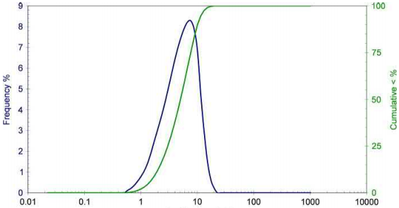
Fig. 3.2 A typical MIM powder particle size distribution where the D10≈2μm, the D50≈5μm, and the D90≈10μm.
If two lots of powders have the same D50, but different D10 and D90 values, the lot of material may behave very differently in compounding, molding, and sintering. A smaller D10 will have more fines and subsequently sinter better, but load poorly into a binder system. A large D90 will have more coarse particles and sinter poorly, and may show distortion or cracking since there are few particle-to-particle contacts per unit volume as the particle size increases. These issues are not of too much concern with gas-atomized materials; however, any elemental powder, particularly those that receive an attrition step to reduce size, may have greatly different D10 and D90 values and cause process difficulties or improper component size and density from one powder lot to the next. MIM powders can be taken from dust collectors of a powder attrition operation, thus variability in the particle size may exist depending on the attrition conditions. Knowledge of the D10, D50, and D90 on each powder lot is critical to ensure that the powders being used are consistent and will behave consistently from one powder lot to the next.
Spherical powders are preferred for the high packing density and flow characteristics of MIM feedstock; however, some advantage in shape retention has been seen with slightly irregular shaped particles. Enhanced shape retention for spherical particles can be obtained by decreasing the particle size to obtain greater particle-to-particle contacts per unit volume. Fig. 3.3 shows the effect of particle shape on the packing density of monosized particles. One can clearly see that the more spherical the powder, the higher the packing density. This also translates to the higher critical solids loading in the MIM feedstock. Consequently, the spherical powders have the potential for less shrinkage than nonspherical powders as a result of their higher packing density and subsequent higher solids loading. Gas-atomized powders, which are spherical, typically have the greatest critical solids loading and the potential for the least shrinkage. Elemental powders, made by chemical reduction or precipitation, typically have the greatest shrinkage since their solids loading is the lowest. Example solids loadings for gas-atomized powders are 60–67 vol%. The solids loadings for chemical precipitated or reduced powders are in the 50–62 vol% range.
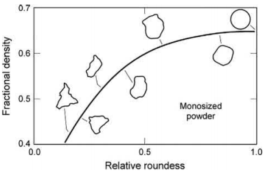
Fig. 3.3 The effects of particle shape on the packing density of monosized particles—the more spherical the powder, the higher the packing density.
Test methods that are typically used for conventional powder pressing such as sieve analysis (MPIF 05, ASTM B 214, ISO 4497), flow rate (MPIF 03, ASTM B 213, ISO 4490), and free flowing apparent density (MPIF 04, ASTM B 212, ISO 3923-1) are not well suited for MIM powders. These methods are appropriate for larger particles that are pressed; however, the MIM process requires powder characterization that is more suited for the smaller MIM powders. Powder characteristics such as pycnometer density, apparent density, tap density, and PSD are better suited for characterizing MIM powders. Other characterization techniques such as Brunauer-Emmett-Teller (BET) surface area may be used in support of some unique applications.
The pycnometer density of the powder provides the theoretical density of the powder and can also provide an indication of issues with internal voids within a powder. For example, if a drop of pycnometer density is observed either within different particle size cuts or from lot to lot, a likely cause could be internal voids due to the fabrication technique. The pycnometer density also provides a practical test to evaluate the powder for any gross changes from lot to lot. Furthermore, the pycnometer density is used when determining the proper powder/polymer mixture or feedstock. Both the powders and polymers can be evaluated by pycnometer density to obtain the proper solids loading in a mixture for predictable shrinkage. For example, the knowledge of the material density allows the weight of the constituents to be used to prepare a feedstock with accurate volumetric solids loading. Typically, tooling size is determined by accurate solids loading and final sintered density; thus, pycnometer density is an essential first step for accurate feedstock determination and can be utilized to minimize the number of iterations required to obtain accurate shrinkages for tooling.
Apparent density is the bulk density of the powder. It provides the mass per unit volume of loose packed powders. This value is a first, low-cost evaluation of a powder to determine consistency from lot to lot. A low apparent density can be an indication of fine particles and a high apparent density can be an indication of large particles. A change in apparent density can also indicate a change in the surface roughness of the powder; for example, atomization satellites may reduce apparent density. Also, if a powder is heavily agglomerated, this may appear as an increase in apparent density.
The tap density is essentially the bulk density of the powder after it has been tapped in a graduated cylinder until no appreciable change in volume is seen. Automated devices exist where the powder is mechanically tapped at a rate of 100–50 taps/ min; typically 500–1000 taps is sufficient to obtain accurate densities. Hand tapping on a rubber pad can also be used if an automated device is unavailable. This density provides information on how the powders pack together and a first indication on how well the powders will load into a feedstock. Typically, the higher the powder’s tapped packing density, the higher the subsequent MIM solids loading.
PSD is typically measured using laser scattering or diffraction techniques for MIM powders. In this technique, the “halo” of diffracted light is measured on particles suspended in a liquid. Essentially the angle of diffraction increases as the particle size increases. The method is good for particles in the 0.1–1000μm range. Fig. 3.2 shows a PSD measured using this technique for a typical MIM powder. Since each manufacturer of these devices uses a numeric algorithm to convert from “halo” to particle size, disparity in size may exist depending on the machine that is used. However, for the particle sizes of importance to MIM, the results obtained on different manufacturing equipment are very comparable. Powder classification for PSD is an important step in the production of powders for MIM since many MIM powders are taken from a larger size distribution of powder and must be carefully removed and measured to ensure that the MIM powders are consistent on a lot-to-lot basis.
There are multiple powder fabrication techniques that can be used to produce MIM grade powders. These techniques primarily consist of the following:
gas atomization;
water atomization;
thermal decomposition;
chemical reduction.
Powders from other methods such as mechanical crushing/grounding are typically used when minor powder additions are needed for designer alloys or in an elemental powder blend to produce a particular alloy. One unique exception is the carburization of pure tungsten powder to produce tungsten carbide grade powders. Table 3.1 lists powder physical attributes, their relative cost, and typical metals and alloys that are produced from these different types of powder fabrication techniques. Further information on particle fabrication techniques can be found elsewhere.
Table 3.1 Manufacturing methods and attributes for MIM powders
Manufacturing method | Relative expense | Example metals or alloys | Particle size (μm) | Particle shape |
Gas-atomized Water-atomized Thermal decomposition Chemical reduction | High Moderate Moderate High/moderate | Stainless steels, super alloys F75, MP35N, titanium, master alloy additives Same as gasatomized previously, except for titanium and titanium alloys Iron, nickel Tungsten, molybdenum | 5-45 5-45 0.2-20 0.1-10 | Spherical Semispherical/ irregular Spherical,spiky Angular, spherical |
Gas-atomized powders are produced by melting the metal or alloy by induction or other method of heating and subsequently forcing the melt through a nozzle. After the liquid metal or alloy leaves the nozzle it is struck by a high-velocity stream of gas, which breaks the melt into fine droplets, these then solidify into spherical shaped particles during free fall. The gas is typically nitrogen, argon, or helium; however, air can be used for some powders. The air-atomized particles show higher surface oxidation; thus, air atomization is not recommended for most engineering materials, particularly those that are difficult to reduce in a subsequent sintering step. Powder free fall takes place in a large container that permits the solidification of the particles prior to their contact with the container wall. If turbulence exists near the nozzle during atomization, small solidified particles will become reintroduced into the atomizing melt stream and result in satellites on the particle surface. These irregularities will interfere with the powder packing density and subsequent flow behavior in a MIM feedstock. Gas atomization can produce a wide distribution of particle sizes, which requires downstream classification such as screening or air classification. Particles that are too large are reused for future atomization or are sold for other powder application such as thermal spray coating or selective laser metal printing. A typical scanning electron microscopy (SEM) image of a gasatomized powder is shown in Fig. 3.4. These particles are known for their spherical shape, high surface purity, and high packing density.
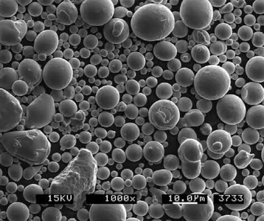
Fig. 3.4 A typical SEM image of a gas-atomized powder stainless steel powder.
Water atomization is generally similar to gas atomization in most aspects except that water and not gas is used to break up the melt stream into fine particles. A highpressure water jet impinges on the melt stream to rapidly break up and solidify the powders. The use of a superheated melt produces the most spherical particles and a higher water pressure results in the finest particles, thus water atomizing at superheated temperatures and at high water pressures are important for powders used for MIM. As with gas atomization, powder size classification is an important step for producing powders for MIM. A typical SEM image of a water-atomized powder is shown in Fig. 3.5. These particles are typically slightly irregularly shaped and show greater surface oxidation than gas atomization particles. The irregular shape does have some advantages for shape retention during debinding. The production rate using water is much higher than that with gas, thus, the cost of the water-atomized material is less than gas-atomized powders.
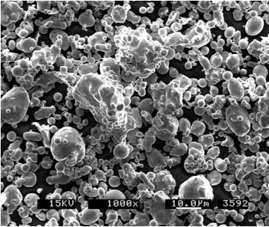
Fig. 3.5 A typical SEM image of a water-atomized powder stainless steel powder.
Thermal decomposition is a chemical decomposition caused by heat and is commonly used to produce nickel and iron powders for MIM. Tungsten and cobalt are also candidates for this technique. This method produces powders that have purity >99% and particle sizes in the 0.2–20μm range. In this process, the metal of interest is reacted with carbon monoxide at high pressure and temperature to produce a metal carbonyl. This metal carbonyl liquid is purified, cooled, and subsequently reheated in the presence of a catalyst, which results in vapor decomposition into a powder. A typical SEM image of a thermally decomposed iron carbonyl powder is shown in Fig. 3.6. These powders typically have carbon impurity that must be reduced in hydrogen prior to use, during sintering, or calculated as an alloying ingredient for low-alloy steels. If the powder is subsequently reduced prior to MIM, the powder must be deagglomerated by milling as the particles are bonded together during reduction. Furthermore, the sintering activity of these reduced powders is not as great as the unreduced powders because the finest particles become sufficiently sintered or assimilated with the larger particles during the reduction process.
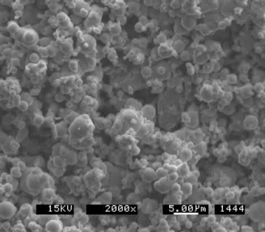
Fig. 3.6 A typical SEM image of a thermally decomposed iron carbonyl powder
Oxide reduction is one of the oldest known methods for producing powders.The process utilizes a purified oxide which is subsequently reduced using a reducing agent such as carbon to form carbon monoxide or carbon dioxide. Hydrogen can also be used to reduce the oxide powder into a metal powder. Particle size can be reduced using a lower reaction temperature; however, the reaction kinetics are slow. The process can be accelerated by using a higher temperature; however, the higher temperature results in diffusion bonds between the particles. This agglomeration must be subsequently removed by attrition or milling to a sufficiently fine particle size. If the particles are not milled, the agglomerated particles will not load properly into a binder system—resulting in high, unstable viscosity and variability in shot-to-shot mass and uniformity during the molding operation. A typical SEM image of a chemically reduced tungsten powder is shown in Fig. 3.7.
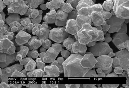
Fig. 3.7 A typical SEM image of a chemically reduced tungsten powder.
There are three primary methods for alloying in MIM: elemental, prealloy, and master alloy. Powder selection is intimately linked with alloying methods for MIM because the powders are either the exact stoichiometry of interest or must be blended to acquire the appropriate stoichiometry.
The elemental method requires a blend of elemental powders in the appropriate ratios to produce the desired stoichiometry. Atomization technique can be used for copper or titanium. Thermal decomposition is used for carbonyl iron and carbonyl nickel. Chemical reduction is used for tungsten and molybdenum. Mechanical grinding and milling is used for milling of electrolytic chromium. Example mixtures could be carbonyl iron mixed with carbonyl nickel for nickel steels, where the carbon can be obtained directly from the carbon impurities in unreduced carbonyl iron. The mixture of iron and nickel can also be used to form magnetic 50Fe/50Ni. Others consist of electrolytic and ground chromium added to iron to form steels and stainless steels. Heavy alloys are also produced using elemental blends—for example the addition of iron and nickel carbonyl powders to chemically reduced tungsten. The practitioner must closely monitor the particle specifications from lot to lot since the methods of manufacturing these particles may produce different PSDs, even if they are in the producer’s specification. Lot-to-lot particle size variability of minor elemental additions, <3%–5% typically, have a less significant effect on the mixture’s viscosity and sintering behavior. However, if the addition is a substantial component in the mixture, the lot-to-lot variability may influence the manufacturability, i.e., injection molding consistency, sintered density, and dimensions.
The prealloy method is the use of a powder that is the exact stoichiometry of the alloy of nterest. The powders for this alloying method are typically gas- or water-atomized. Example alloys are stainless steels, super alloys, and titanium alloys. These alloys are typically very consistent in particle size. Plasma atomization of wire can also be used to produce spherical alloy powders of titanium, nickel, zirconium, niobium, and tantalum.
The master alloy method is the use of an elemental powder with a gas or wateratomized powder, where the gas or water-atomized powder is enriched in certain alloying elements. An example would be one part of a gas-atomized 55Cr38Ni7Mo master alloy mixed with two parts carbonyl iron powder to produce a 316L stainless steel. When the elemental powder is mixed and alloyed with the enriched atomized material, the enriched elements are diluted to the stoichiometry of interest. This method is common for most stainless steels and for some low-alloy steels. Slightly inferior properties have been observed for stainless steels; however, the fine carbonyl powder used in the master alloy technique provides a means to enhance debinding strength, since a finer elemental powder provides more particle-to-particle contacts and a lower sintering temperature due to the smaller particle size. Care must be taken in the selection of the elemental addition; for example, if unreduced carbonyl iron powder is used for a stainless blend, the carbon may not be entirely removed in the sintering operation unless an appropriate sinter cycle is selected to allow for reduction of this powder.
Contact: Cindy Wang
Phone: +86 19916725892
Tel: 0512-55128901
Email: [email protected]
Add: No.6 Huxiang Road, Kunshan development Zone, JiangsuShanghai Branch: No. 398 Guiyang Rd, Yangpu District, Shanghai, China