This chapter describes how the part is processed to obtain the solid metal part after it has been molded. This section would also apply to parts made by other consolidation methods using a feedstock or a metal/binder mixture where the binder initially holds the powder together.
To understand debinding, it is necessary to understand the thinking behind the formulation of the metal injection molding (MIM) feedstock. The feedstock is a mixture of binders and metal powders that makes the mixture moldable in an injection molding machine and later permits the easy removal of the binders such that the molded shape is retained after binder removal and sintering. A detailed explanation is given in the book.
From the debinding viewpoint, the molded part has no porosity and the feedstock used is made basically of two binder components. The purpose of the first component, which is easily removable at a low temperature, is to create a network of pores through which the second binder may escape at a later stage. The second binder, also known as the backbone polymer, holds the powders in place, retaining the part shape, until the temperature is high enough for diffusion bonds between the metal powders to take place so that the molded shape is retained when all the binders are gone. Other organic components are added to enable the binders to wet the powder surfaces and to create a bond between the two major binder components. These components are either removed with the primary binder or in some cases may need to be removed in the same manner as the backbone binder.
7.1.1 Binder systems
The wax-based feedstocks were the first to be developed but many different binder systems have been developed since. Each system has a unique debinding process because of the different polymers used in the binder systems.
All these different binder systems have been developed based on the principles earlier. Here we discuss the most commercially prevalent systems in order to understand how best to remove the polymers. These binder systems are listed as follows:
The first systems based on the Strivens (1960) and Weich (1980, 1981, 1986) patents used waxes and oils for the primary binder and a polyolefin as the secondary binder with an addition of a rubber-like material, such as, styrenes and Kraton, to bond these two materials. Binder systems based on waxes are still the most widely used feedstock type in the United States.
The primary binder used is water-soluble. Feedstocks based on these systems are becoming more popular as halogenated and other organic solvents are becoming more difficult to use.
The primary binder easily evaporates or sublimes at room temperature or at a relatively low temperature; for example, water used as the primary binder, when it is mixed with agar to form a gel in the process, the main ingredient of traditional moth balls, is used as the primary binder in a system developed at the Pacific Northwest National Laboratories. These feedstocks show promise because almost no equipment is needed for primary debinding.
The MIM feedstock is a very precise mixture governed by the solids loading or the volumetric ratio of metal powders to binders. This ratio governs the viscosity or the flowability of the feedstock and also the amount by which the part made from this feedstock will shrink after debinding and sintering. The repeatability of the shrinkage is maintained by tightly controlling this ratio when the feedstock is made.
Although the water-soluble system and the wax-based system were developed almost in the same time frame, the wax-based system proliferated faster as Weich and his partners went their own way and the initial model was to license the process to grow the industry.
In the wax-based system, the process was limited by the equipment available at that time. The primary binders were thermally debound very slowly in an electrically heated air oven. This low-temperature burnout (LTB) oven required a very slow ramp of about 0.5℃/min and long hold times at the peak temperature of about 200℃, followed by oven cooling to about 70℃ before the carts were removed from the oven. Primary binder removal processing times through the LTB oven for orthodontic parts weighing between 0.05 and 0.10 g were close to 24 h. Hence, part thickness was limited to obtain a reasonable processing time. Also, the long exposure to low debinding temperatures degrades the backbone binders, making the part extra fragile.
The parts were then transferred to a high-temperature debind (HTB) oven, which ran under a reducing or protective atmosphere, where the secondary binder was removed and the parts pre-sintered at temperatures up to about 1050℃ to reach sufficient strength to be handled and moved to a third furnace where sintering to the full density would take place. The third furnace was usually a vacuum furnace which could reach the high temperatures required to densify the parts quickly. This choice stemmed from the fact that the furnaces with protective atmospheres that could handle the large amount of binder released did not go to a high enough temperature to reach the full density desired and sintering vacuum furnaces could not handle the binders released.
Today the MIM process has been improved and requires less time, although there are still a few companies who are manufacturing parts using the old three-step method described earlier. The process used today uses one piece of equipment to perform the primary debinding depending on the feedstock type used in the process. The parts are then moved to a "debind and sinter" furnace where the parts go through the secondary debinding operation, followed by ramping to the sintering temperature. Most of these furnaces for the standard MIM materials reach 1450℃ and the furnace processing time is usually less than 24 h.
Most feedstocks have at least two binders. When the primary binder, sometimes called the soluble binder, is removed a network of interconnected pores is formed. The polymer evaporating at the higher temperature uses this network of interconnected pores to escape without cracking or degrading or causing sudden stresses that degrade or distort the molded part.
During thermal debinding of the primary binder, as the temperature rises, increasing amounts of binder evaporate from the entire binder mass. Sudden evaporation of a binder fraction with no clear exit path causes the part to rupture and lose integrity. Hence, the evaporation rate of the binder must be extremely slow to prevent part rupture. This makes thermal debinding of the primary binder a difficult and timeconsuming process that has been discontinued by most MIM processors. The desired method is to remove the primary binder starting from the outside of the part, moving in to the core, in such a manner that the secondary binder is affected as little as possible. Since this is achieved by solvents, organic or water, as well as the catalytic method, these three types of feedstocks have found the widest applications. Debinding of these binder systems are discussed in detail in this chapter.
The Allied Signal/Honeywell feedstock lost momentum when Honeywell bought Allied Signal. This material needs only a drying oven that flows air over the parts to dry the moisture for primary debinding. Also, the water content of the binder played an important role in the solids loading of this feedstock. A small change in the water content could cause an unacceptable change in the shrinkage making the process out of control. Although this process requires little capital expenditure for primary debinding, there seem to be no users left today.
The binder system from Pacific Northwest Laboratories which uses naphthalene that sublimes at room temperature as the primary binder, is relatively new and it is not known if any company is using this process commercially as this time. These systems have not been discussed.
Most feedstock manufacturers provide a value of the green feedstock and a weight loss value after primary debinding. Some manufacturers go further and provide a theoretical brown density. This theoretical "brown density" is the density value of the feedstock without the primary binder content. If the density of the feedstock is known and the theoretical density of the brown feedstock is available, measurement of the brown density of the part (density of the primary debound part) using a helium pycnometer is the most accurate method to determine whether the part has been properly debound or not. The density method eliminates the issue of poor mold filling of the part and catches this error before the parts are debound. The method of calculating the green and brown densities are given as follows:


where
V=Volume
M=Mass
ρ=Density
P1=Metal powder 1
P2=Metal powder 2
Pn=Metal powder n
B1=Binder 1 (primary)
B2=Binder 2 (secondary)
Bn=Binder n (secondary)
Note, that the time required to debind is a function of the debinding method, the size of the part, as well as the particle size of the powders used to make the part. For example, the same part molded from 20μm gas atomized copper powder, 10μm carbonyl iron powder, and 1μm alumina powder using the same feedstock required 3, 6, and 22 h of solvent debinding time respectively for complete wax removal. Of course, if the feedstock flow rate is maintained because the powders were used to fill the same mold, as the particle sizes are reduced there is a corresponding drop in the solids loading of the feedstock. This is another reason for the increase in the debind time.
Initially solvent debinding units were probably heated open tanks. Environmental regulations have forced most of these open tanks out of use in most advanced countries. Solvent debinding units permitted by the regulations were modified parts-washing units or machines used for dry cleaningclothes.These are already fitted with proper environmental controls and have closed-loop circulation and distillation systems which prevent the release of the solvent to the atmosphere and the exposure of the workers to the solvent. Ninety-nine percent plus of the solvent vapors are extracted by drying the parts under vacuum and using a carbon canister from which the captured solvent may be reused. Only a very small fraction of the solvent used is released to the atmosphere per run. The required process steps are programmed into the programmable logic controller (PLC) which controls the solvent debinding unit. A simplified schematic diagram for the solvent debinding system is shown in Fig. 7.1. The parts are immersed in clean solvent in the cleaning chamber forthe settimeto dissolve allthe primary binders.Whenthe binders are allin solutionin the solvent, the solvent is moved from the cleaning chamber to a "dirty tank." Meanwhile, the parts are dried in the chamber under vacuum. The dirty solvent is transferred from the "dirtytank" in smaller batchesinto a distillation unit. The distilled clean solventis storedin the "cleantank" for reusein the next cycle.Fig. 7.2 shows such a typical solvent debinding system marketed by Elnik Systems (Elnik, n.d.) around 2011, where all the tanks, distillation unit, pumps, and filters are hidden behind the panels.
![1667525031664194.png 3$F]2QPJ[M$1S3WLN1A760I.png](https://www.atmsh.com/Uploads/image/20221104/1667525031664194.png)
Fig. 7.1 Schematic diagram of a solvent debinding system.
Some of the older solvents used are 1,1,1-trichloroethylene, perchloroethylene, and n-propyl bromide. Since these halogenated chemicals either deplete the ozone layer or are carcinogens, in most countries their vapors must be totally captured. Many countries have either banned or are banning the use of ozone depleting chemicals and require the use of non-ozone depleting organic solvents, such as hexane, alcohols or acetone, which are considered to be green solvents. Since these organic solvents are flammable, the modern solvent debind units are set up as explosion proof units.
In the supercritical solvent debinding (Appliedseparations, n.d.), process the waxes are removed using liquid carbon dioxide as the solvent at about 50-70℃. A high pressure is required to keep carbon dioxide liquid at these temperatures. This process is very attractive because the solvent is carbon dioxide, which is also considered to be a green solvent, and the dissolution of the wax requires a very short time. After the soaking process, the liquid carbon dioxide is removed from the chamber and the pressure is reduced, which allows carbon dioxide to evaporate. The waxes are left behind in the solid form and can easily be cleanly removed. However, pressures as high as 350 bars are required to keep the carbon dioxide in the liquid form at 70℃. Special highpressure vessels are required, which has limited the diameter of the chambers, limiting the use of this process to very small parts. The costs of making conventional size chambers are prohibitive and have slowed commercialization of this process.
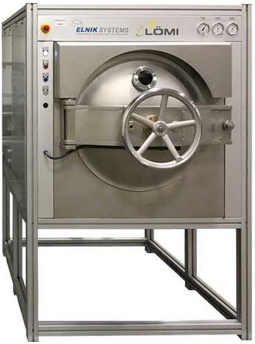
Fig. 7.2 Typical solvent debinding system marketed by Elnik Systems.
The catalytic debinding (CD) oven works with the Catamold type binder system only. The Catamold type binder system comprises two major ingredients: (a) polyoxymethylene (POM), which is also known as polyacetal or polyformaldehyde and (b) polyolefin. POM, whose formula is (-H2-C-O-)n, breaks down into formaldehyde, (H2-C]O), in the presence of nitric acid between 100℃ and 140℃ and leaves behind the metal powder skeleton held together by the remaining polyolefin. The formaldehyde formed is explosive in the presence of air, hence a nitrogen flow is maintained to remove all oxygen from inside the oven. The ratio of nitric acid vapor to nitrogen must be below 4% for a reasonable rate for the catalytic reaction and not cause an explosion. Although formaldehyde itself is toxic, it burns cleanly and easily. Hence, all CD ovens have a burner to burn the formaldehyde coming out of the exhaust of the oven.
There are many manufacturers that make CD ovens and all of them work based on the previously mentioned principle. Most of these are batch ovens, although Cremer Furnaces is at least one manufacturer that makes a continuous CD oven in tandem with their continuous sintering furnace. Fig. 7.3 shows a CD oven manufactured by Elnik Systems. The Elnik CD ovens are the only ones controlled by a computer (PC). The main computer screen of this oven is shown in Fig. 7.4. The main screen shows all the process combinations possible. This permits the user to make programs using all the variables in the process and allows the recording of all the programs and the trends for all the debinding runs performed by the oven.
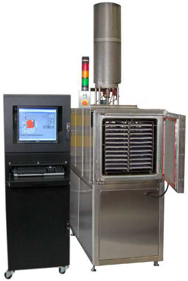
Fig. 7.3 A catalytic debinding (CD) oven.
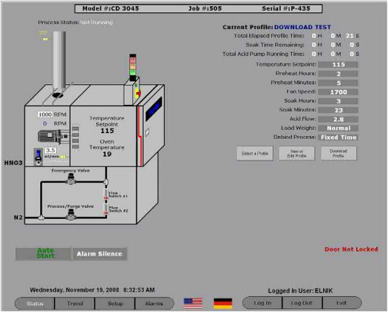
Fig. 7.4 The main computer screen of an Elnik CD oven.
All feedstock manufacturers provide a minimum weight loss percentage that needs to be achieved for complete debinding in their product data sheets. While green densities are given, brown densities are not mentioned. Ryer Inc. and TCK Feedstock provide the weight loss and go further to provide the green and brown densities for accurate debinding data.
In case of the water-soluble systems, the primary binder is water-soluble while the secondary binder is not. Parts made from the water-soluble binders are immersed in a tank until all the primary binders are removed. After all the binders are removed, they are put in an air oven to dry. After complete drying, the parts are ready to move on to the next stage. Most of these units are home-made ones where readily available water baths have been modified to dissolve the primary binder and separate air ovens are used for drying. Attempts to automate this system resulted in machines more expensive than the simple water baths and drying ovens together and did not bring any time savings for debinding.
It has been found that most water-soluble feedstocks take a longer debind time compared to solvent debind systems or CD systems and the newer entrants to MIM are staying away from these feedstocks.
The basis for debinding and the equipment used for the three major types of commercially used feedstocks have been discussed. In the case of solvent debinding, water being the solvent for water-soluble materials, the dissolution of the solute into a solvent depends on the solubility of the solute, the temperature of the solvent, and the solute concentration gradient. Hence, the debinding parameters depend on the specific binder and solvent combinations. Some of the following issues require attention.
The debinding temperature or the solvent temperature when the parts are immersed; when the primary binder is liquefied, dissolution rates are much faster than in the solid state.
Reaction or interaction of the solvent with the secondary or other tertiary binders at the debinding temperature should not cause part distortion from the melting of a binder constituent or by adsorption of the solvent by the secondary binder.
The solvent should not have a high vapor pressure at debinding temperatures and become a fire hazard. This is especially true for modern organic solvents with low flash points. Often such equipment must be housed in separate explosion-proof rooms. Table 7.1 shows some of these solvents with their boiling points and flash points. Most organic solvents have very low flash points. Also included in this Table are some of the popular halogenated solvents and their boiling points. The halogenated solvents do not have flash points.
Care must also be taken regarding local waste disposal issues when releasing solvents or distillation wastes which are contaminated by the primary binder. Also, just because a binder is water-soluble does not mean the solution may be dumped into the sewer system.
In the case of all the binder systems discussed, the reaction starts from the outside of the part and proceeds towards the center of the part. For the solvent systems, the binder must dissolve into the solvent and for the catalytic reaction system, the catalyst must be present at the surface for the reaction to proceed. Hence, in all cases, the debinding processing time is a function of the thickness of the part in conjunction with the other individual process parameters, such as, binder type, particle size, particle size distribution and solids loading.
Table 7.1 Typical solvents and their boiling points
Solvent | Boiling point (℃) | Flash point (℃) |
Organic | ||
Acetone | 56 | -18 |
Hexane | 69 | -7 |
Heptane | 98.4 | -4 |
Isopropyl alcohol | 82 | 12 |
Halogenated | ||
n-Propyl bromide (NPB) | 70 | None |
Trichloroethylene | 87 | None |
Perchloroethylene | 121 | None |
n-Methyl pyrrolidone (NMP) | 204.3 | None |
Table 7.2 Debinding temperature and rates for different binder systems
Primary binder | Secondary binder | Primary debind method | Debind temperature (℃) | Debind rate (mm/h) |
Wax-based | Solvent |
|
|
|
Paraffin wax | Polypropylene | Heptane | 50 | 1.5 |
Synthetic wax | Polypropylene | Perchloroethylene | 70 | 2 |
Water-soluble |
|
|
|
|
Polyethylglycol (PEG) 200 | Polypropylene | Water | 40 | 0.3 |
PEG | Polyacetal | Water | 60 | 0.5 |
Catamold |
|
|
|
|
Polyacetal | Polyethylene | Nitric acid catalyst | 120 | 1.5 |
Table 7.2 shows multiple binder systems with their debinding method, temperatures used for debinding, and approximate debinding rates achieved for regular MIM parts. As the part thickness increases to over 10mm, a significant decrease in the debind rates may be observed; therefore, extra time will be needed to completely debind the parts.
The parts after removal of the primary binders are often referred to as the brown parts.At the low temperatures where the primary binders are removed no diffusion bonding between powder particles takes place. It is the secondary binders, also known as the backbone binders, and interparticle friction that hold the powder particles together and maintain the shape provided by the injection molding after the primary binders are removed. Removal of the primary binders generates a network of interconnected pores within the brown molded part which enhances the ability of the secondary binder to be removed without causing defects in the components.
The secondary binders are removed thermally. This is achieved by heating the parts slowly to the temperature where the secondary binder evaporates and holding the parts at this temperature until all the binders are removed. In almost all metal systems, the binders do not burn because the furnace is under a reducing or inert atmosphere and no oxygen is available. In case of ceramics that are debound and sintered in air, the binders would probably burn as they leave the part.
More than one temperature hold may be necessary if there is more than one secondary binder present. Often, a small amount of the primary binder is also left behind inside and on the surface of the part after the primary debinding by the solvent or water debinding process. A short hold for this remnant primary binder is also customary.
A thermo-gravimetric analysis (TGA) of the feedstock, before and after primary debinding, is the best method to determine the hold temperatures for the secondary binders. The TGA is usually ramped at the ramp rate the parts would see during thermal debinding in the sintering furnace. During thermal debinding in the sintering furnace, the ramp rates are slow. Holds are placed at each of the temperatures where the weight loss for each of the components is completed. Table 7.3 gives some debinding temperatures used for some typical secondary binders. Fig. 7.5 shows a typical curve from a TGA run of a 4140 wax-based feedstock. Based on this analysis holds were placed at 380℃, 440℃, and 540℃, which resulted in the carbon content of the alloy coming out at the middle of the specification. Hold times are a function of the maximum wall thickness of the part and will depend on the individual binder system and the powders used.
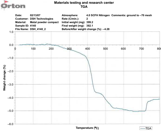
Fig. 7.5 TGA curve for a solvent debound wax-based 4140 MIM feedstock
Table 7.3 Thermal debinding temperatures of common secondary binders
Secondary binder | Thermal debind temperature (℃) |
Polypropylene Polyethylene Polyacetal | 450-500 500-600 300-450 |
By the end of the thermal debinding cycle, tiny diffusion bonds are formed between the metal powder particles which augment the interparticle friction and help retain the shape given to the part by injection molding. In case of ceramic molded parts, the particle sizes are of the order of one magnitude finer than that of metal powders. The finer particles result in narrower pores, when longer debind times are necessary for removing the binders. For ceramics, no sintering takes place at the thermal debinding temperatures. Ceramic powder particle sizes used are of the order of 10 times finer than the metal particle sizes. Hence, interparticle friction is the dominant cause in ceramics, that helps maintain the shape after removal of all the binders.
There are several reasons for incomplete binder removal but they all stem from two factors, wrong debinding temperature and/or insufficient debinding time at temperature. Gas flow rate is also an important factor in debinding. Insufficient gas flow prevents the evaporated binders from being removed and allows the binders to be retained in the part. The result is the same effect as the binder being removed at the wrong temperature. Gas flow is a processing matter which depends on the binder system and content, as well as the powder particle size and distribution.
The correct debinding temperature is best determined using a TGA, as explained earlier. The hold duration is a function of the binder system, the amount of binder, the pore size and length (which are a function of the particle size and distribution), and the wall thickness of the part. However, despite the heat transfer and thermodynamics classes, many engineers forget that just because a thermocouple reads 600℃ (or whatever temperature the hold is supposed to be at), it does not mean that the entire load inside a furnace is at 600℃. It takes time for the furnace temperature to equalize at all regions inside the furnace load and the hold time start point must be counted from the time only after the furnace temperature has equalized.
If the parts inside the furnace do not dwell at the correct temperature for the correct duration, there is binder inside the parts when the furnace moves on to the next ramp to reach the sintering temperature. The remaining binder comes out at temperatures higher than where it should have been removed and at this point the heating rate is also faster. Depending on the amount of binder left, the following may happen.
Sudden evaporation of binder can occur leading to cracking and/or blistering of the parts.
Rapid evaporation of the binder can occur, causing the binder to be deposited on the insulation of the heating elements and the furnace, followed by conversion of the binders into soot and graphite with rapid rise in the furnace temperature. Multiple deposits in this manner reduce the life of the hot zone of the furnace by coating the heater insulations, thus shorting the heating elements to ground. The life of the heating elements could also be reduced. These would require rework of the furnace at a reduced interval requiring additional capital expenses.
When a rapid temperature rise occurs inside the parts, the polymer cracks and leaves soot deposits inside the parts. This results in a high carbon content and a change in the desired chemical composition of the alloy. The composition change leads to property changes in the parts produced, such as partial melting or slumping, distortion, low ductility and brittleness, high hardness, poor corrosion resistance, etc.
It is thus extremely important to remove the secondary binder properly to obtain the desired properties in the part and to obtain the optimum life for the furnace.
The aim in MIM is to remove the binder from the parts and convert the powder mass into a strong metal part without losing the molded shape. This is the major difference between plastic molding and powder injection molding. The final process of converting the part into a strong mass is achieved by sintering. The parts need to be subjected to a higher temperature in a suitable atmosphere for this to happen.
Sintering is a term used in many industries. The current author's (S.B.) first contact with the term was in an extractive metallurgy class where students learnt about iron ore fines and limestone fines being mixed together and fired to make a solid but porous sintered mass that could be easily charged into a blast furnace. The iron pillar of Delhi located in India, made in the late 4th century AD and brought to its current location in the 11th century, is said to be powder forged from magnetite ores. The last time I saw it, it had no rust and you could touch it. Today there is a fence around it to prevent erosion from the touches of the daily tourists. Sintering is used to make ceramics, refractory metals, spark plugs, cemented carbides, self-lubricating bearings, filters, electrical contacts, insulators, oxide nuclear fuels, structural, magnetic, aerospace, and medical parts to name a few, with many more possible applications in the future.
There are thus many different definitions depending on the industry that is served.Provide a working definition of sintering as follows: "Sintering is a thermal treatment for bonding particles into a coherent, predominantly solid structure via mass transport events that often occur on the atomic state. The bonding leads to improved strength and a lower system energy." According to the glossary in ASTM B 243-13(ASTM, 2010) Section 3.4.1: Sinter, v. "to increase the bonding in a mass of powder or a compact by heating below the melting point of the main constituent."
There are many different theories on the mechanisms of sintering. Although an older work, an excellent review is provided. The theories are far behind the sophistication and degree of the practice of sintering. Book Sintering Theory and Practice does an excellent job in trying to fill this gap and explain the various mechanisms of sintering. For those who like explanations without mathematics, Pease and West (2002) provide a comprehensive explanation of sintering.
Sintering lowers the surface energy of the powder mass by the formation of interparticle bonds which reduce the surface area. With the growth of the interparticle bonding significant changes occur in the pore structure resulting in the improvement in many properties, such as, strength, ductility, corrosion resistance, conductivity, and magnetic permeability. These changes are of primary interest in industrial applications including MIM. Also, in MIM, the dramatic elimination of pores results in large shrinkages and the variables in the entire process must be within control to obtain the process repeatability that keeps the sintered dimensions within the desired tolerance limits.
Atoms move and vibrate all the time, even in the solid state. This movement combined with the need to remove free surfaces to reduce surface energy results in the formation of solid bonds between particles. Heat enhances this effect. As the free surfaces are removed, pore migration occurs by the movement of vacancies using grain boundaries as conduits. Further energy reduction occurs by the reduction of grain boundaries by grain growth, after which further homogenization may occur by bulk diffusion. If the process continues for infinite time the two spheres in the model should end up as one sphere, the state of the least energy.
Sintering theories assume that sintering is taking place between two spheres of the same size and material, which are at a point contact, under isothermal conditions. Mass flow in response to the driving force for sintering is determined. Under these conditions mass transport may occur by surface transport mechanisms and by bulk transport mechanisms.
Fig. 7.6 depicts the two-sphere sintering model. The spheres touch, then the neck forms and this neck begins to grow. Initially surface transport mechanisms predominate by moving atoms from surface sources, namely, evaporation, and condensation (E-C), surface diffusion (SD) and volume diffusion (VD). In all these cases, the atoms travel from the surface of the particles and end up at the point of contact of the particles, increasing the bond between particles without any change to the distance between the two particles but causing the formation and some growth of the neck between the two particles.
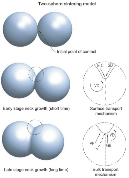
Fig. 7.6 Two-sphere sintering model showing different stages of progression of sintering and mass transport mechanisms.
With later stage neck growth, the centers of the two spheres begin to get closer to one another and shrinkage is observed. Bulk transport mechanisms predominate during this time and provide for neck growth and elimination of pores using atoms from inside the two particles by plastic flow (PF), viscous flow, grain boundary (GB) diffusion, and VD. Only bulk transport mechanisms can cause shrinkage.
Here is a brief overview of the individual transport mechanisms.
Evaporation and condensation: materials with high vapor pressures or those reacting with the sintering atmospheres to form a volatile species are potential candidates for sintering controlled by the evaporation and condensation process. NaCl, TiO2, H2O, and Si3N4 are typical examples showing this behavior. For most commercial metallic systems, the vapor phase transport contributions are negligibly small.
Viscous flow: this is the usual sintering mechanism for amorphous materials. The viscosity of most amorphous materials declines with increasing temperature and any external pressure aids the process. Since there are no grain boundaries and the amorphous structure is like that of a liquid, full of defects, bonding progresses until curvature gradients are eliminated.
SD: surfaces of crystalline solids are full of defects and are never smooth, even after the best polishing techniques. The atoms are moving from one defect site to another and end up at the point of contact between the two particles to form contact and neck formation thereby reducing the surface energy between the two particles. Smaller particles result in increased curvature and lower activation energy for the process. The activation energy is also lower than that for the bulk diffusion processes. The practical application is that it causes the formation of bonds between particles at low temperatures which help retain the shape of loosely bound powder aggregates, as in cases like slurry casting of powders, binder assisted additive manufacturing and powder injection molding.
VD: this occurs by the migration of atoms through interstitial defects such as dislocations and vacancies from inside the grains in a crystalline material. VD can cause both neck formation and densification.
GB diffusion: grain boundaries are made up of huge quantities of defects that stem from the mismatch between the orientations of adjacent grains. These boundaries become the conduit for atoms to move to close pores, or conversely vacancies from the pores to move out to the surface. GB diffusion has a lower activation energy than VD and hence is the mode of mass transfer that occurs before VD.
PF: this occurs by the annihilation of vacancies by dislocation climb and its occurrence is debated when there is no external force. Under isothermal sintering conditions it is considered to be a transient process. PF is the major transport mechanism in the presence of an external pressure.
The sintering stages represent the changes in the powder mass after consolidation into a shape to the final densified object. Not all applications are the same, for example for pressed and sintered powdered metal structural parts, the high green densities are achieved by pressing the particles together at high pressure and large contact surfaces are present before sintering. On the other hand, for filter or self-lubrication bearing applications a specific pore size is the most wanted part property and the parts are not sintered to be fully dense. MIM represents a condition like the sintering of a loose heap of powder, where all the stages of sintering apply.
The first stage is adhesion, rearrangement, and repacking which begin with weak van der Waals'forces. Small amounts of rotation and twisting occur at high temperature to obtain lower energy states with respect to grain orientations.
The next stage is the growth of a sinter bond between contact points formed by the previously mentioned process and leads to the initial stage neck growth. This is the initial stage of sintering where the early portion of neck growth occurs but there is no or only minor densification taking place.
This stage is followed by the intermediate stage, where neck growth occurs resulting in densification. The necks lose their identity and pores become rounded but are still interconnected.
During the final stage of sintering, the interconnected open pores close and become isolated closed pores. Grain growth also occurs as the pores become closed, which causes the diffusion process to slow down. While the previous stages are relatively rapid, the final stage of sintering slows down asymptotically as the density passes the 95% mark and nears 99% depending on the system and the sintering temperature.
Fig. 7.7 shows a scanning electron micrograph of a sintered iron-cobalt-vanadium Permandur pre-alloyed material, with powder particles on the surface showing neck growth and interparticle grain boundaries. These particles show some interconnected pores with the fully sintered area in the background. The fully sintered structure in the background shows that the particle identities have been lost and larger intra-particle grain boundaries caused by grain growth have formed with progressive sintering.
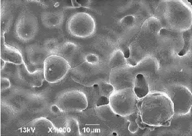
Fig. 7.7 SEM of a sintered iron-cobalt-vanadium Permandur pre-alloyed material, with powder particles on the surface showing neck growth and interparticle grain boundaries. In the background is the sintered structure where particle identities are lost and larger intraparticle grain boundaries are seen.
Fig. 7.8A shows the microstructure of a pre-alloyed cobalt-chrome (F 75) alloy MIM part as sintered at 1200℃ for 1 h under hydrogen. The grains are small and there is a considerable amount of porosity, some of which is inside the grains. Fig. 7.8B shows the structure of the same alloy as sintered at 1300℃ also for 1 h under hydrogen. The grains are considerably larger than in the parts sintered at 1200℃, the total porosity is considerably less, and most of the pores are inside the grain boundaries.
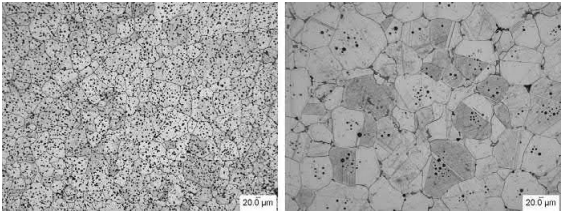
Fig. 7.8 (A) Cobalt-chrome alloy (F 75) sintered at 12008C. (B) The same cobalt-chrome alloy (F 75) sintered at 13008C.
The sizes of the individual pores are also larger. Sintering has progressed between the two temperatures causing grain growth, pore migration along the grain boundaries, and pore coalescence and isolation inside the grain boundaries.
While sintering models have also been made with other configurations, such as sphereplate, wire-wire, cone-plate, cone-cone, etc., sintering practice involves many particles, not all of the same size but with different particle sizes, and not all spherical but with the shapes of the particles varying, depending on how the powders are made. Heating conditions are never isothermal. This is further complicated by the presence of other elements, which come from the powder manufacturing system or which are added on purpose for specific reasons. Diffusion of one element into another plays a major role as does the phase diagrams involving the different elements. Ternary or quaternary systems often show low melting eutectics at temperatures lower than that for similar binary systems which would bring in the effect of the presence of liquid phases.
When powders are consolidated into shapes the contacts formed between particles depend on the consolidation process, as well as the particle shape, particle size, and the particle size distribution. The term consolidation process is a catch-all phrase for all powder systems, for powders that could be pressed in a die or isostatically; hot, warm or cold; slip or slurry cast;injection or compression molded with a binder;loose powderin dies, additive metal manufacturing incorporating a binder system and so on. In case of consolidation with pressure, the pressure causes plastic deformation in the cold, warm or hot conditions and contacts between particles are enhanced. In the other processes without external pressure, they are packed to a near ideal random packing approximating the tap density of the powder. Conditions in MIM and additive metal manufacturing systems correspond to this group of consolidation without external pressure.
The powder mix used to make parts is not necessarily a homogeneous prealloyed material but can also be of elemental powder. How these elements affect one another also has important effects on the sintering process, depending on how the elements react with one another. Adding elemental powders may often be the least expensive method to make the sintered alloy. However, in some cases the reaction between some elements may leave no other recourse than blending a master alloy with an elemental powder to make this particular alloy. There are several possibilities when elemental powders are added to one another.
The two components are mutually intersoluble, when homogenization takes place. The formation of stainless steels from the elemental powder blends or master alloy elemental powder blend is one such example.
The base (matrix) is soluble in the alloy addition but not the other way around, which leads to enhanced sintering. The addition of a small percent of Ni to W results in what is referred to as activated sintering, which allows W to be sintered at temperatures as low as 1400℃.
The alloy addition is soluble in the matrix (base) but not the other way around. This results in the addition to be dissolved in the matrix but since the matrix is not soluble in the additive, the additive is left full of voids and porosity which results in swelling. This is a situation you would want to avoid during sintering.
Both phases are mutually insoluble; this is the situation in case of composite materials when the properties of the two components are necessary for the application. One such example is oxide dispersion strengthened alloys when Al2O3 is dispersed in a metallic matrix, such as certain Incoloy products.
The formation of a liquid phase which needs to be discussed separately.
Many sintering systems generate a liquid. Often an element or compound is added which has no reaction or solubility with the matrix, even when it is a liquid, when they do not even wet the matrix. Some examples are lead in bronze or MnS in stainless steels. Such liquids do not aid or affect the sintering process but remain as droplets inside the matrix which sinters by the solid-state diffusion process.
On the other hand, when a liquid with even a limited reaction with the matrix is present, the liquid pulls the particles together and the capillary forces cause densification. This is the first step of liquid-phase sintering when the liquid wets the matrix. The liquid also provides a diffusion path with mass transport rates much faster than those by solid state diffusion. Hence, the formation of too much liquid can cause the rest of the skeleton to collapse; the part slumps in such cases. However, a controlled amount of liquid phase is especially beneficial to the sintering process because the faster mass transport rates result in rapid densification.
Liquid phases may be present in two forms; when the liquid phase is present during the entire sintering hold period it is known as a persistent liquid phase. The other form is when the liquid phase solidifies during the sinter hold period, and this is called a transient liquid phase.
Persistent liquid-phase sintering is classified in two types: the first is when mixed elemental powders are used to make up the part and one component on heating forms a liquid. Typical examples are heavy alloys, such as W-Fe-Ni where the alloy is heated to form liquid Fe-Ni in which the W has limited solubility, or WC-Co where Co dissolves some WC and forms an eutectic but WC dissolves a very minimal amount of Co. Fig. 7.9 shows a photomicrograph of a 90W-7Ni-3Fe alloy showing rounded grains of tungsten in a Ni-Fe-W alloy matrix. During sintering, the Fe-Ni melts and dissolves tungsten in the liquid phase resulting in the rounding of the tungsten particles. The excess tungsten beyond the solubility limit precipitates inside the liquid. This is a typical example of solution-re-precipitation during liquid-phase sintering.
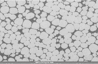
Fig. 7.9 Photomicrograph of a 90W-7Ni-3Fe alloy showing rounded grains of tungsten in a Ni-Fe-W alloy matrix, an example of solution-re-precipitation during liquid-phase sintering
The second type is supersolidus liquid-phase sintering (SLPS) and occurs when a pre-alloyed powder is heated above the solidus to result in a small amount of liquid that causes melting of the surface and the grain boundaries within the particles, causing solution re-precipitation and densification. A typical example of where SLPS is used is in the case of M2 type tool steels. Fig. 7.10 shows a typical structure of an as-sintered M2 tool steel, with small globules of the carbide phase in the matrix and some larger amounts along some of the grain boundaries.
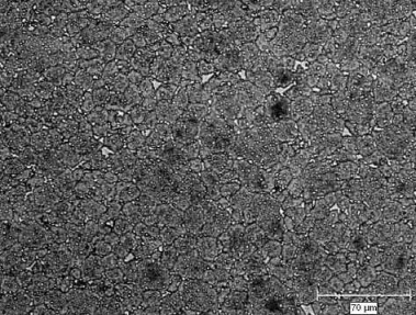
Fig. 7.10 Typical structure of an as-sintered M2 tool steel, with small globules of the carbide phase inside the grains and some larger amounts along some of the grain boundaries
There are two types of transient liquid-phase sintering. The first is reactive sintering, when an element A forms a compound with another B with an exothermic reaction resulting in heat and the compound AB. One such example is NiAl. The second is when the other transient liquid phase disappears because of diffusion of an element to form a solid solution, such as carbon which had formed a eutectic with iron and chromium, which solidifies when the carbon diffuses into the matrix.
While everything on sintering discussed earlier applies to MIM, the previously mentioned models are based on conventional powder technologies. MIM does have some special requirements. In MIM, the binder is used to carry the powder into the molds and make the desired shapes. Hence, MIM powders are much finer than powders used in conventional powder metallurgy. Powders used in conventional powder technologies are usually smaller than 150μm with about 25% fines where the fine powders are less than 45μm. Typical MIM powders that are based on carbonyl iron powders have a D90 of about 15μm while typical pre-alloyed powders have a D90 of about 22μm.
Some components have also been made with a D90 of about 45μm, but this is on the high side and requires special check rings in the molding machines with extra-large clearances. In case of micro MIM parts, where the parts or certain features of the parts are in the micrometer range, particle sizes used are even finer and powders having D90 of 2 and 3μm are commercially available for such applications. These fine particles represent a high amount of surface area and hence a large amount of surface energy, which influence the sintering and densification mechanisms for MIM.
The powder particle size has a direct relationship with the surface area of the powder.To understand the effect of surface area in MIM, let us calculate the surface area of 1 g of carbonyl iron powder, assumed to be made up of 100% of 10μm particles, to simplify the calculations. Then,

where the density of carbonyl iron powder is 7800 kg/m3.
Hence,

Thus, the surface area of 1 g of the 10 powder is the number of particles in the 1 g of powder times the surface area of one powder particle, which works out to be about 7692 cm2 .
To give a perspective, 1 g of 10μm iron powder, which is a little over a pinch of powder, has a surface area of approximately 7692 cm2 (8.3 ft2 ) the size of a small bridge table with sides 87.7 cm (almost 3 ft) wide. Despite what the calculations show, this fact is difficult to either visualize or comprehend, when compared to 1 g of iron as a single spherical particle, which has a diameter of 6.25mm and a surface area of 127.8mm2 , or a square with sides measuring 11.3mm only.
In a typical D90 10μm powder used in MIM, most of the particles are finer in size and the actual surface area is larger than that of the 10μm only powder used for the previous calculation. This is a huge area of exposed metal atoms with this humongous surface energy. While this surface energy aids the sintering process, this huge surface area also leaves the material prone to oxidation with exposure to the ambient atmosphere. Some powders become pyrophoric, that is, are prone to instant combustion. In most cases, a can of open powder would show increasing oxygen content with increasing time of exposure. For this reason, sintering atmospheres and hence the material of furnace construction play very important roles in the properties of the parts being processed.
The extremely large surface area of MIM powders results in oxidation of the powder surface and the extent depends on the reactivity of the metal powder used with the ambient atmosphere. For certain extremely reactive metals like titanium, which reacts with oxygen, nitrogen, hydrogen, and carbon, i
Contact: Cindy Wang
Phone: +86 19916725892
Tel: 0512-55128901
Email: [email protected]
Add: No.6 Huxiang Road, Kunshan development Zone, JiangsuShanghai Branch: No. 398 Guiyang Rd, Yangpu District, Shanghai, China