To make a part consistently and repeatedly by MIM, every step in the MIM process must be repeatable, from the powders used to the sintering step. In each step, there are several process variables. These variables must be controlled within a window which yields the desired results. In case of debinding, every bit of the binder must be removed, which means there is a minimum processing time and any additional time beyond the minimum has almost no negative effect. In case of sintering, which is controlled by diffusion rates for the different materials, time and temperature are the major variables. The final result after sintering of the parts must produce the correct part dimensions. This should also result in the correct density and shrinkage that produce the correct physical properties. Continuation of the sintering time beyond a certain level has little effect on the density but could have a profound effect on grain growth. Extremely large grains could have a detrimental effect on some physical properties.
Fig. 7.11 shows the effect of grain growth. The same M2 material as in Fig. 7.10 is seen here, except it was sintered for a longer time. While the grains have grown considerably, most of the liquid phase has migrated to the grain boundaries resulting in heavy carbide deposits. This would reduce the toughness and the ductility of the sintered material.
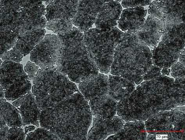
Fig. 7.11 Structure of an as-sintered M2 tool steel, over sintered, showing grain growth and the majority of the carbide phase along the grain boundaries.
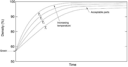
Fig. 7.12 Plot of sintered density in relation to time of sintering.
Fig. 7.12 shows a plot of density with time. The starting material has a density corresponding to the green density. After sintering, the part shrinks and densifies to the upper ninety-something percent range with time. Since the progress in densification is diffusion dependent, it is asymptotic and slows with time as the density nears 100%. Increasing the temperature moves the curve up and to the left. In a production furnace, the temperature is not the same at every place and there are internal variations because of the distance of the part from the heating elements, as well as for other reasons, such as gas flow, shielding effects, and so on. Under these real conditions, a box, bounded by a minimum time and temperature and a maximum time and temperature, which results in densities (or critical dimensions) that fall within the part specifications defines the results of acceptable sintering. Such a hypothetical box is also marked in this figure.
Table 7.4 List of MIM materials
Material | Debind temperature (℃) | Preferred debind atmosphere | Sintering temperature range (℃) | Preferred sintering atmosphere | Note code |
Iron | |||||
FN02 FN08 FN50 Silicon iron | 250-650 250-650 250-650 250-650 | N2 N2 N2 H2 | 1180-1290 1180-1290 1180-1290 1180-1300 | N2 N2 N2 H2 | A A A B |
Tool steel | |||||
H11 M2 M4 M42 T15 | 250-650 250-650 250-650 250-650 250-650 | N2 N2 N2 N2 N2 | 1200-1275 1180-1250 1180-1250 1180-1250 1200-1270 | N2 N2 N2 N2 N2 | A A A A A |
Steel | |||||
1040 4340 4140 8620 42CrMo4 100Cr6 | 250-650 250-650 250-650 250-650 250-650 250-650 | N2 N2 N2 N2 N2 N2 | 1100-1270 1100-1270 1100-1270 1100-1290 1100-1290 1190-1290 | N2 N2 N2 N2 N2 N2 | A A A A A A |
Stainless steel | |||||
17-4PH 316L 410 420 440C 17-7PH 18/8 304 Panacea | 250-650 250-650 250-650 250-650 250-650 250-650 250-650 250-650 250-650 | H2 H2 H2 N2 N2 H2 H2 H2 H2 | 1200-1360 1250-1380 1250-1375 1200-1340 1200-1280 1200-1340 1200-1340 1250-1375 1180-1275 | H2 H2 H2 N2 N2 H2 H2 H2 H2/N2 | B B B A A B B B B |
Tungsten-based | |||||
WC W-Cu | 250-650 250-650 | H2/N2 H2 | 1250-1390 1150-1400 | H2/N2 H2 | A B |
Copper-based | |||||
Pure Cu Bronze Spinodal | 250-650 250-650 250-650 | H2 H2 H2 | 950-1050 850-1000 850-1000 | H2 H2 H2 | C B B |
Precious metals | |||||
14-22 kt gold Sterling silver | 250-650 250-650 | H2/N2 H2/N2 | 850-1000 850-1000 | H2/N2 H2/N2 | A A |
Titanium | |||||
Ti Ti 6/4 | 250-650 250-650 | H2/N2 H2/N2 | 850-1000 850-1000 | H2/N2 H2/N2 | A A |
High-temperature alloys | |||||
Inconel 718 Hastelloy X HK-30 GMR-235 Haynes 230 | 250-650 250-650 250-650 250-650 250-650 | Ar H2 Ar/H2 Ar Ar | 1200-1280 1200-1270 1200-1280 1200-1280 1200-1260 | Vacuum H2 Ar/H2 Ar/H2 96Ar/H2 | C C C C C |
Note: A, can be processed with no difficulties in either graphite or in refractory metal furnaces; B, can be processed with reduced properties in graphite furnaces under N2 or with optimum properties in refractory metal furnaces under H2; C, must be processed in refractory metal furnaces.
MIM may be used to make parts from a wide variety of materials. Table 7.4 shows a list of materials which have been used to make parts by MIM. This list is not all inclusive. Most often, powder availability for new materials depends on the big question: are parts made from this material cost effective? Today, with the growth in 3D printing and as more parts for aerospace type applications being made by 3D printing and MIM, there has been a spurt of specialty alloy availability for MIM type applications.
As mentioned earlier, the large surface area could be the cause for a large amount of oxygen to be picked up by the powder. The oxygen removal from the part depends on the reactivity of the material. The type of furnace used would depend on the reactivity of the metal and the atmosphere desired in the furnace.
Precious metals
In case of gold and some other precious metals that do not tarnish, no oxides are formed. In case of silver, the oxides break up to release oxygen below sintering temperatures. In such cases, the oxides are no problem. But in most of the other materials processed a reducing agent is needed to remove the oxygen. The two reducing agents used for most materials are carbon and hydrogen.
Metals whose oxides are easily reducible
Copper, tin, iron, nickel, cobalt, manganese, molybdenum, and tungsten are examples where the oxides are easily reduced by both carbon and hydrogen. However, carbon must be added in the solid form or be present in the form of carbon monoxide. Since carbon monoxideis the form of oxide that is more stable at higher temperatures, using gases containing carbon monoxide, such as endo-gas, does not provide a satisfactory reducing atmosphere because two carbon monoxide molecules break down into carbon dioxide and carbon, which is deposited as soot. Tungsten and molybdenum will form carbides. Copper and bronze parts arethe exception where endothermic gases may be used. Adding carbon in the solid form introduces the question: what happens when you add too much carbon? The answer depends on the alloy system and the phase diagrams involved.
Carbon steels
Sintering carbon-containing steels to obtain the same desired carbon content from batch to batch requires a critical control of both the oxygen and carbon contents of the mixture. The oxygen content of the powder will cause the carbon content to be depleted because of the reduction of the oxides by carbon. To achieve the desired carbon content, for example, 0.4% in a 4140, the powder must have an extra amount of carbon that reduces the oxygen content of the powder. These parts are usually sintered in nitrogen to provide an inert atmosphere. Argon or even a vacuum may be used if nitrogen pick-up is not desired. Hydrogen will reduce these oxides, but it will also remove all the carbon in the alloy by the formation of methane. Hence, hydrogen is not used where carbon control is essential. In a graphite furnace, hydrogen may not be used above 800℃ because hydrogen will attack all the graphite inside the furnace from the hot zone to the heating elements and the graphite retort or load carrier used to carry the parts.
To prevent carbonyl iron powder from oxidizing further between its packaging and use and to prevent agglomeration of the particles, some manufacturers put a thin layer of silica over each iron particle right after making the powder. This works well with carbon steels because further oxidation of the iron powder is minimized, which allows for easier carbon control. The carbon reduces the silica to silicon during the sintering process and the silicon dissolves in the matrix. Since the layer of silica is thin, the amount of silicon added is well within the standard specifications for the alloys.
High alloyed steels containing carbon
Heavily alloyed carbon-containing steels, such as tool steels and 420 and 440 type martensitic stainless steels, have larger carbon contents than low alloyed steels. These are mostly pre-alloyed powders and often have layers of chromium oxides, silicon dioxide, and oxides from the other elements, which are all reduced by the carbon in the alloy. These are usually sintered in neutral atmospheres, such as nitrogen or argon or a vacuum.
Corrosion resistant low carbon steels
Oxides of chromium and silicon require a high temperature and a very low moisture (product of the reduction process) content to be reduced by hydrogen. If carbon is added for sintering in a neutral atmosphere, any excess carbon will form chromium carbide and the purpose of having a low-carbon stainless steel will be defeated. Hence, stainless steels and other high-chromium-containing alloys should be sintered in a hydrogen atmosphere. This requires the use of a refractory metal batch furnace or a high- temperature continuous furnace, such as a pusher or a walking beam with 100% hydrogen atmosphere. Carbon containing martensitic stainless steels are sintered in a neutral atmosphere and are treated differently from the low carbon stainless steels.
MIM stainless steels have been made in three different ways: by using elemental powder blends, by using a master alloy blended with carbonyl iron powder, and by using the pre-alloyed powder. Fig. 7.13 shows the fracture surface of a 17-4PH alloy made from a carbonyl iron powder and master alloy blend that was sintered in a nitrogen atmosphere. An energy dispersion X-ray analysis (EDXA) shows that the large number of spherical inclusions seen are silica, which probably come from the silica coatings used on the carbonyl iron powder. The same mixture sintered in hydrogen showed no such inclusions. A pre-alloyed powder sintered in vacuum also showed spherical inclusions, but to a smaller amount, as seen in Fig. 7.14. These inclusions were chromium oxides as determined by EDXA and arise from the surface oxide layer over each 17-4PH powder particle. Again, the same material sintered in hydrogenshowed no inclusions. Corrosion properties were the best for hydrogen sintering and worst for the masteralloy-based material sintered in nitrogen, while vacuum sintering resulted in mediocre corrosion properties. MIM stainless steels made in the three-step process where the final sintering was done in a vacuum also showed chromium oxide spheroids because the pre-sintering temperature was not high enough to reduce the chromium oxides by hydrogen. Many manufacturers worldwide produce stainless steel components in vacuum or nitrogen in graphite furnaces. The resulting mechanical properties are within acceptable limits, but the corrosion properties are sub-optimum because of the oxide inclusions. The presence of these oxide inclusions also results in a poorer polish on finishing compared to parts made in hydrogen that have no oxide inclusions. Of course, optimum corrosion properties are not needed for all applications, for example cell phones and laptop computer hinges must last the life of the appliance, which is taken to be a couple of years.
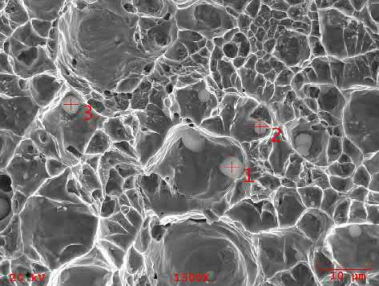
Fig. 7.13 Fracture surface of a 17-4PH material made from carbonyl powder blended with master alloy powder sintered in nitrogen showing many spherical inclusions.
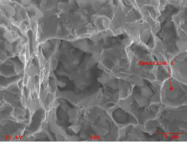
Fig. 7.14 Fracture surface of gas atomized 17-4PH powder sintered in vacuum shows a smaller number of inclusions compared to that seen in Fig. 7.13.
Tungsten alloys
Although tungsten is listed earlier where it can be reduced by both carbon and hydrogen, tungsten is a carbide former and any excess carbon will result in carbides. Hence, heavy alloys, where carbides are not desired, are usually sintered in hydrogen. Since the oxides of tungsten are reducible at relatively low temperatures wet hydrogen is often used to remove any excess carbon and prevent the formation of blisters. Most tungsten alloys are sintered by either activation sintering with a sintering aid or by a liquid phase that involves a solution-reprecipitation process as discussed earlier in this chapter. Tungsten carbide and other hard metals are usually bonded with either cobalt or iron-nickel type binders. Here too the method of sintering is solutionreprecipitation. Usually a nitrogen atmosphere with a small amount of hydrogen is used for sintering carbides in order not to lose carbon from the carbides.
Titanium and its alloys
Titanium is considered to be the most difficult to sinter with respect to controlling the oxygen content because titanium dioxide cannot be reduced by either carbon or hydrogen. Hence, any oxides formed on the powder particle surface remain in or on the part. Titanium will also react with carbon, hydrogen, and nitrogen. Graphite furnaces should be avoided because of the carbon atmosphere present. Traditionally, titanium has been sintered under high vacuum between 10-5 and 10-6 mbar. At DSH Technologies, experience has shown that, in case of a batch furnace with a retort inside the hot zone, pure argon, with a purity of a couple of ppm or better as obtained by using a heated getter in line before the furnace, with a low partial pressure sweep of between 50 and 70mbar may also be used to obtain similar, if not better, results (Banerjee & Joens, 2016). Parts run in argon showed better ductility and lower oxygen contents and slightly lower strength than the parts run in vacuum, where all strength levels were within the specifications. Densities obtained were similar at 4.23 g/cm3 . Fig. 7.15 shows the structure of MIM Ti-6Al-4V sintered under argon.
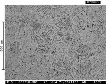
Fig. 7.15 Structure of MIM Ti-6Al-4V sintered under argon.
High-temperature alloys
High-temperature alloys or superalloys are another challenge. They contain chromium for oxidation resistance and elements like aluminum, vanadium, tantalum, niobium, titanium, zirconium, hafnium, and other elements added as gamma prime formers, which strengthen the matrix of the materials by the precipitation of the gamma prime intermetallic compounds that are stable at high temperatures. Hydrogen would form hydrides in case of tantalum, niobium, titanium, zirconium and hafnium and cause hydrogen embrittlement in superalloys. Carbon is also not desired in these materials as the carbides would reduce the amount of gamma prime precipitates. Oxides of aluminum, titanium, zirconium, and hafnium cannot be reduced by either carbon or hydrogen. Vacuum or argon is the atmosphere of choice in most cases.
Other materials
The discussion so far has been limited to conventional materials. MIM has been attempted for refractory type materials too, such as rhenium, niobium, molybdenum, platinum, etc. One limitation for such materials is the furnaces needed, namely a furnace with tungsten shields, furniture, and heating elements. This makes the furnace very expensive because tungsten cannot be cut or punched the way most metals can. Powder availability is another factor which depends on the applications.
Many materials that have been studied in the laboratory have not translated into large volumes of MIM parts. One such example is titanium and its alloys. Papers have been written on MIM titanium for years but the actual volume of MIM titanium parts remained a very small quantity with just a few manufacturers world-wide for a long time. The quality of powder needed is extremely tight and hence the powders were expensive. As more titanium is being made by 3D printing, powder quality and availability has improved. Prices have come down and there are more players in the MIM titanium alloy field. AP&C, now part of GE Additive, have more than doubled their capacity of producing titanium powders. There are at least a couple of manufacturers now whose entire operations are dedicated to only MIM titanium parts.
Sintering temperatures used in MIM are usually close to the melting range of the alloys and in some cases also involve a liquid phase. To prevent any reaction between the parts and the charge carriers, a layer of inert ceramic is used as a barrier between the two. While continuous furnaces use a ceramic charge carrier, that is usually not the case for batch furnaces. The charge- carrying shelves in a graphite furnace are usually also graphite. Direct contact of graphite in several alloying systems would result in the formation of a low melting eutectic. In case of refractory metal furnaces, molybdenum or a molybdenum alloy is used as shelving material. Molybdenum reacts with ferrous materials to form a liquid phase. Hence, in both the graphite and metal hot zone batch furnaces, a non-reactive barrier, such as a ceramic, is a must to prevent reaction.
Alumina-based ceramics are the most widely used for most materials except for titanium alloys which react with alumina. Alumina goes through a phase transition around 900℃. Rapid cooling through this region causes the alumina to crack from the stresses due to this phase transformation. Hence, the 96% alumina grade is the least expensive and most common material used. Zirconia-toughened alumina (ZTA) is also gaining popularity because of its higher strength and the absence of the stresses generated during rapid cooling through this temperature range.
Titanium and its alloys are placed on stabilized zirconia. Since titanium has a greater affinity towards oxygen than most of the other elements, the purity of the raw materials is very important to minimize the adsorption of oxygen by the parts from the setter materials. Zirconia stabilized with yttria (YSZ) is the best among the usual materials. Calcia-stabilized zirconia has been used successfully, but the chances of the calcia having impurities is greater than that of pure yttria. High-purity yttria plates have also been used but these are even more expensive and difficult to find than the YSZ plates. Traces of typical impurities found in ceramic materials, such as Al2O3 Na2O, SiO2, FeO, Fe2O3, etc., all give up the oxygen content to the titanium during sintering and reoxidize when the plates are in the atmosphere. Hence, titanium parts do pick up a small amount of oxygen from most zirconia plates during sintering.
Since MIM components are sintered at high temperatures, the material has limited shape retention strength. The forces exerted by gravity are enough to distort the parts unless they are properly supported. Hence, most designers try to build in a flat surface on which the part may be staged.
When there are no flat surfaces available there are two options.
Add appendages to the part to create a flat surface. These additions would have to be machined to bring the shape to the original design, adding a recurring cost. Fig. 7.16 shows a part where an appendage has been added to create the flat staging surface desired. The mark on the part shows an approximate position from where the machine cut will be made.
Create a part-specific surface with ceramics. The cost for such ceramics would depend on the complexity and how the shaped ceramic is created.
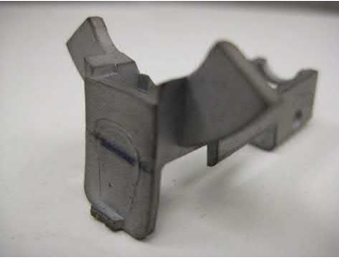
Fig. 7.16 Appendage added to the part in front to obtain a flat surface. The added section is cut from about the mark on the part
When the part has a complex shape and machining is not an option then a contoured ceramic is chosen. Fig. 7.17 shows the setter created for a high-end spoon concept to be made by MIM. A concept sketch is shown for a setter for a specially shaped part in
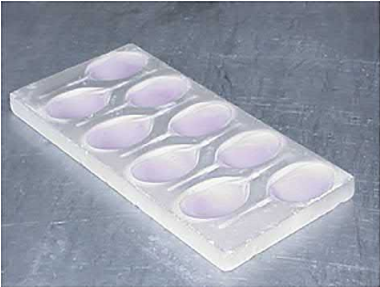
Fig. 7.17 Setter for a high-end spoon concept.
Fig. 7.18 These special setters are part-specific and cannot be used for any other part. Other simpler setters, such as a rectangular groove for an overhang or a V-groove for cylindrical parts, may be used for simpler parts.
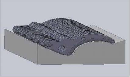
Fig. 7.18 Setter concept for a special part.
The special setters may be made in three different ways.
They may be machined or ground to have the special contour opposite to that of the part. For a few samples, a machinable ceramic may be used, but if the need is to manufacture thousands of parts when hard ceramics are essential, the setters become very expensive.
Another method is to take a machinable ceramic, such as, ZAL 45 from Zircar Ceramics (Rath has a similar product), machine the contour, and then coat the contoured setter with a slurry of fine ceramic particles, dry and sinter the setter at a temperature between 1600℃ and 1700℃ to obtain a hard material that no longer sheds powder. This is less expensive than machining hard ceramics.
The third method is to make a reverse mold and cast a ceramic slurry into the mold. Then the ceramic is dried and sintered to form the final shape. The base of the setter would be ground flat. This is the least expensive of the three methods.
Ceramic setters do add a significant overhead cost to the parts. If a design change of the part to create a flat surface allows the part to perform its function without ceramic setters, then this may be the more economical way to make the part.
Today MIM furnaces carry out two functions: removal of the secondary binder followed by ramping up and holding at the desired high temperature for sintering. These furnaces have evolved from the three-step process used when MIM was first invented.
The first of the three steps is the removal of the primary binders. During the second step, the secondary binder was removed. Since this required a higher temperature, usually between 400℃ and 600℃, a protective atmosphere was necessary, and the equipment had to deal with the large amount of binder by products being released during the process. To give the parts handling strength, the parts needed to be pre-sintered at temperatures between 600℃ and around 1100℃. In the laboratory, it is not unusual to use lower temperatures of 600-900℃, while in production it is more the norm to go close to the maximum temperature capability of the furnace, usually up to 1150℃, to carry out the reduction of the oxides present to the maximum ability. In the third step, the parts were heated up to between 1250℃ and 1400℃ to obtain the final desired density. These high- temperature furnaces were vacuum furnaces which could not deal with the large amounts of binders released during secondary debinding, because of which the intermediary second step was necessary.
The major drawbacks with the three-step process are the double handling of the parts and the time needed to process the materials. The parts had to be cooled down to be handled and moved to another furnace. This required restaging the parts because the two furnaces were not designed to work with one another.
As the owners of the Wiech process separated and set up their own shops, variations in the process began to show. Multi Metal Molding in San Diego, CA used a continuous mesh furnace for secondary debinding and presintering and a continuous pusher furnace for the sintering to final density. Form Physics in San Diego, CA also used a similar system. Although Multi Metal Molding was dissolved somewhere in the late 1980s or in the early 1990s, the continuous furnaces evolved to become one unit which combined secondary debinding with sintering.
Brunswick in Deland, FL wanted to eliminate the time taken to remove the parts from one furnace to another and decided to make their own furnace. They came up with a bell jar furnace where an Inconel retort was heated by an exterior removable furnace core. The Inconel retort limited the maximum sinter temperature to 1250℃, pushing the material to its usable limits. Stainless steels were sintered in pure hydrogen at 1250℃. The major drawbacks were the time per cycle with 6-10 h at final temperature, the frequent reworking of the base plate of the Inconel retort to maintain shape, and the inability to process carbon-bearing steels. This process too was licensed to a number of companies. FloMet, which bought Brunswick, was still manufacturing its furnaces in house. FloMet has since been sold to the ARC MIM Group of Companies which also bought Advanced Forming Technologies (AFT).
A couple of manufacturers started out making carbon-bearing steel parts. They used graphite vacuum furnaces run under a partial pressure of nitrogen. The vacuum furnaces were fitted with claw type dry pumps that were not affected by the secondary binder. These were the first one-step debinding and high-temperature sintering furnaces. The drawbacks of these furnaces are that processing under hydrogen was not possible and the pumps required frequent cleaning because the binder traps did not function effectively. Again, low-carbon materials, such as stainless steels, cannot be processed to obtain optimum corrosion properties since hydrogen atmospheres may not be used in graphite furnaces.
A few manufacturers tried to convert sintering furnaces with molybdenum hot zones into MIM furnaces. These early attempts led to limited success until Randall German, then at Pennsylvania State University, asked Claus Joens of Elnik Systems to develop a MIM furnace based on his vacuum furnaces. Elnik Systems developed the first truly MIM batch furnace that could sinter under vacuum, hydrogen, nitrogen, and argon or a mixture of two of these gases at a desired partial pressure from 15 to 900mbar or even under high vacuum, if the furnace had the high vacuum option.
The continuous furnaces used in MIM are based on the high-temperature sintering furnaces used in conventional sintering but adapted for the large amounts of binders emitted by the parts. The first section is a low- temperature section for debinding and requires a special gas sweep to ensure the binder breakdown products do not reach the sintering section of the furnace. The travel speed of the parts and hence the duration of stay in this section must allow the parts to be debound completely. The debind duration is set for the thickest part cross-section the furnace will see. The parts then move on to the high-temperature sintering section of the furnace. The travel rate of the plates also fixes the sinter time at temperature. Typical sintering temperatures used are in the 1300-1400℃ range. After the sintering zone, the parts go through a cooling zone before they come out of the furnace.
CM Furnaces in the United States made the first pusher furnace for MIM while Cremer Furnaces based in Germany used their walking beam design for MIM. Some other furnace makers have been making continuous furnaces for MIM relatively recently.
Fig. 7.19A shows the schematic diagram of a pusher furnace and Fig. 7.19B shows a picture of a CM pusher furnace (Cmfurnaces, n.d.). Fig. 7.20A is a schematic diagram of a walking beam furnace and Fig. 7.20B shows a Cremer walking beam furnace (Cremer-furnace, n.d.)

Fig. 7.19 A CM pusher furnace.
Continuous furnaces are built with refractory bricks inside a gas-tight metal shell. Hence, it takes a while for the temperature inside the furnace to stabilize, therefore start-up times after a shutdown are long. If you are making millions of the same part with the same material, the continuous furnace is the best option. But this is not the best if you need to make sintering temperature changes for different materials or make debinding hold time changes for different part thicknesses. Also, whether you are running parts or not, you will need to run gas to protect the heating elements, which makes idling of these furnaces very expensive.
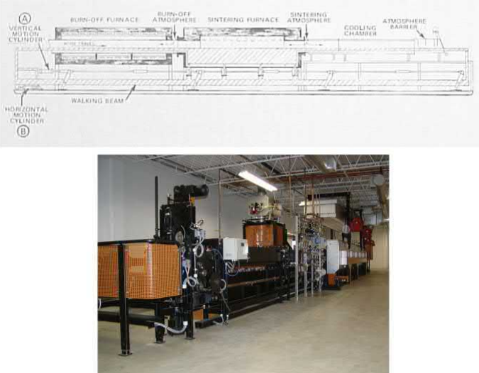
Fig. 7.20 (A) Schematic diagram of a walking beam furnace. (B) A Cremer MIM Master walking beam furnace
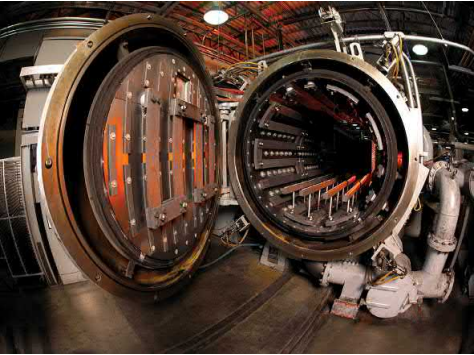
Fig. 7.21 A typical graphite furnace with a graphite hot zone and graphite elements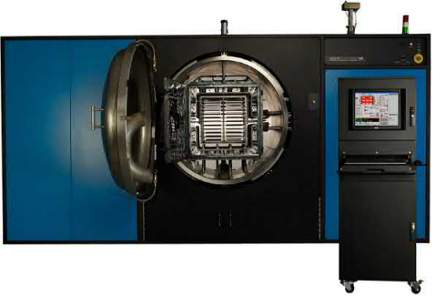
Fig. 7.22 A refractory metal MIM furnace with a molybdenum hot zone and retort
Batch furnaces are popular with those working with different materials and part mixes that require production flexibility. Fig. 7.21 shows a typical graphite batch furnace. In this case, a graphite box shelving with parts loaded on shelves is loaded into the hearth. Three zones are used to control the temperature and you use your experience to judge when the entire load mass reaches constant temperature. This type of a furnace works well for carbon-containing steels because the furnace is usually equipped to use a nitrogen atmosphere only. Hydrogen would react with the graphite to form methane and hence may not be used. This limits the materials that may be processed to obtain optimum properties. Since these furnaces run under nitrogen or vacuum only, safety requirements are less than those furnaces running under hydrogen. Because graphite costs less than refractory metals and is easier to machine, and as the safety requirements are considerably less, graphite furnaces are relatively inexpensive.
One furnace manufacturer offers a metal hot zone furnace that runs at 100% hydrogen, but this runs at 15mbar throughout the process. 100% hydrogen at 15mbar is below the explosive limit of hydrogen. Hence, no safety requirements are required to contain hydrogen explosions inside the furnace. This makes the furnace relatively cheap and attractive. However, 100 % hydrogen at 15mbar does not reduce the oxides of silicon or chromium.
Centorr in the United States was the first company to offer refractory metal sintering furnaces for MIM with the two-step process but their debinding system was not optimal. While Centorr has improved their MIM furnace, MIM is a small percentage of their total furnace sales. Thermal Technologies in Santa Rosa, CA was also one of the first to be in this field, but Thermal Technologies also wanted to make MIM parts and was subsequently sold and had to leave the MIM business. Elnik Systems, which formerly manufactured vacuum furnaces for the defense industry, is the only batch furnace manufacturer specializing in equipment for the MIM industry, though there are many companies offering MIM furnaces. Fig. 7.22 shows a refractory metal MIM furnace (Elnik, n.d.) with a molybdenum hot zone and a molybdenum retort. The furnace can process most materials to their optimum properties using hydrogen or argon or nitrogen atmospheres or vacuum. The furnace is completely computer controlled and uses the Microsoft Excel program to create and download the furnace recipes. Even trap cleaning is automated and is accomplished by the simple push of a virtual button on a computer screen. The ability to run hydrogen mandates certain safety measures in the furnace, the refractory metal market is volatile, and the raw materials are costly. These requirements make these furnaces more expensive than graphite furnaces.
Graphite furnaces have been around for a long time and several manufacturers, such as GM Furnaces, Centorr and AVS in the USA make these for the MIM industry. Elnik Systems also make a MIM furnace similar to their refractory metal furnace with a graphite hot zone and retort with characteristics and controls similar to the all-metal furnace for those wanting to process carbon-containing materials only.
Whether a batch furnace or a continuous furnace should be used depends on the application. Continuous furnaces can provide a large throughput of parts and are chosen when throughput is the major requirement. All parts in the same line of travel see the same temperature, although it is difficult to introduce survey thermocouples on parts.
Gas consumption in a continuous furnace is high, because of the large openings on both sides of the furnace, but power consumption is lower because of the smaller cross-section of the furnace compared to a batch furnace. The major drawbacks of the furnace are their inflexibility regarding materials and part size, the high cost of idling, and long times needed to start up or cool down these furnaces for repair and maintenance. These furnaces also require a large amount of floor space.
Batch furnaces are very flexible regarding the size of parts and the materials to be run.When there are no parts to run there is no power or gas consumption. During normal running, gas consumptions are lower and power consumptions are higher than in continuous furnaces but there is no power consumption during cooling or idling. Temperatures inside the batch furnace can be directly measured using survey thermocouples on the parts.
Graphite furnaces are limited with respect of the processing atmospheres that may be used in them. Hence, the flexibility of graphite batch furnaces regarding the ability to process different materials is less than those with refractory metal hot zones and heating elements. Refractory metal MIM furnaces are the most flexible among all the different furnaces available because they permit the use of hydrogen atmospheres, argon or nitrogen, as well as high vacuum if this option is included. This permits these furnaces to process high-carbon materials, stainless steels, and cobalt-chrome alloys, as well as superalloys, titanium and its alloys, and intermetallic materials with the proper choice of atmospheres.
Whether a batch furnace or a continuous furnace is used, the basic profile remains the same. The principle is to heat up a brown part slowly to the temperature where each of the individual secondary binders evaporates and hold the temperature long enough for all the binders to be removed completely. In case of a batch furnace, a slow ramp is used because a fast ramp causes the temperature at the center of the furnace to lag even more and this lag depends on the thermal load inside the furnace. In case of a continuous furnace, the ramp rate is a function of the travel speed of the parts inside the furnace. Here the distance of the parts from the heat source is relatively small, so the large lag between the outer edges and the center of the furnace in case of the batch furnaces is not observed. Once all the binders are eliminated the temperature is ramped to the sintering temperature, where the parts are held for a period between 1 and 4 h depending on the desired density. The exact temperatures would depend on the boiling point of the different binders and the sintering temperature of the material being sintered.
Both batch and continuous furnaces are being used to make parts with excellent properties in the industry.
MIM feedstocks are made with two major components, the primary one that comes out easily, starting from the outside of the part and movinginto the part, resulting in the opening of pore channels. The secondary binder component holds the powder particles together as the temperature rises until small interparticle diffusion bonds begin to form within the part. These bonds, together with interparticle friction, result in sufficient strength ofthe partto retainits shape atthe highertemperature whenthe secondary binder begins to vaporize, and the vapors may escape through the open pore channels created by the removal of the primary binder. Three types of feedstock are in commercial use today:
a wax-based feedstock where the wax is removed with an organic solvent;
a polyacetal-based feedstock where the polyacetal is removed by the catalytic reaction in presence of nitric acid vapor;
one where the primary component is water-soluble.
Sophisticated PLC controlled primary debinding equipment is available for the wax and polyacetal-based feedstock types. These equipments result in automated and repeatable processing with full documentation capabilities for quality systems for the aerospace, automotive, and medical device industries. In case of the water-soluble feedstock parts, automated equipment costs were much higher but did not speed up the process compared to the conventional tanks and air ovens being used at present.
Secondary debinding is a thermal process which used to be carried out in a separate second step. The parts were then sintered in a third step, typically in a vacuum furnace. Today most of the MIM parts are debound and sintered in the same equipment. Hold temperatures for thermal debinding of the secondary binder are best determined by running a TGA on a brown part run at the heat-up rate used for debinding. Hold times depend on the binder material(s), part thickness, and the particle size of the powders.Incomplete debinding at the hold temperatures causes the binders to come out rapidly at higher temperatures, which could affect the parts in respect of the shape integrity and carbon content, as well as the life of the heaters and hot zone of the sintering furnace.
Sintering is the process by which bonds between the particles occur and the MIM part shrinks to the desired size. The theories, which are based on simple two-particle or other simple models, are behind the practice of sintering. Mass transport during sintering may occur by surface transport mechanisms or bulk transport mechanisms. Solid state sintering occurs in the following stages for loose packed powders: first, adhesion, rearrangement, and repacking; then a sinter bond grows between particles and forms the neck between particles; then neck growth continues with densification until finally pores become closed, diffusion slows, and grain growth begins. While most materials sinter in the solid state only, sintering in the presence of a liquid phase depends on the type of liquid and the reactivities between the liquid and solid phases. In certain alloy systems, the liquid phase enhances the sintering process and in some other high temperature melting alloys, such as some tungsten alloys, a liquid phase must be present for the particles to sinter.
In practice, sintering happens between many particles that are not all of the same size and not spherical. There are minor compositional variations within the same material and added alloying elements may be present. Most systems are not simple binary ones. When sintering and homogenization are happening together, the equivalent phase diagram helps in understanding the process. Solubility and diffusion rates between the constituents play major roles. Liquid-phase formation could also aid sintering.
MIM powders are smaller than powders used for conventional powder metal applications. A 1 g of 10μm spherical powder has a surface area of 7692 cm2 (8.3 ft2), that of a small bridge table. This is a huge amount of exposed area which easily absorbs oxygen from the atmosphere. The amount of oxide formed depends on the reactivity of the metal. This surface needs protection from oxidation and those oxides already formed need to be removed, if possible. Hence, sintering atmosphere plays an important role in MIM. Hydrogen, nitrogen, argon or vacuum may be used to protect the material depending on the metal being processed.
Most materials can be processed by MIM. Powder availability drives the economics. The type of furnace and protective atmosphere used is a function of the reactivity of the materials being sintered. Carbon-containing steels and stainless steels may be processed in graphite furnaces, but low-carbon stainless steels and chromiumcontaining alloys should be processed in refractory metal or continuous furnaces under a hydrogen atmosphere at high temperatures to obtain oxide-free structures and optimum properties. Titanium and superalloys require high vacuum or argon partial pressures in refractory metal furnaces.
MIM parts must be placed on a non-reactive ceramic material on top of the charge carrier to prevent interaction with the parts and the charge carrier material. MIM materials have no strength at sintering temperatures. Designing in a flat surface on which the part may be placed is the most economical option. If a shaped surface contour on the part is the only option, special setters must be constructed to nest this shape.
Both continuous and batch furnaces are available for the debinding and sintering of MIM parts. Continuous furnaces are preferred when very high throughput is the most important criterion for the operation, whereas when the operation needs to be more flexibleto accommodate different materials and part sizes, batch furnaces are chosen. Graphite and all-refractory-metal- type batch furnaces are both used to make MIM parts although the materials processed optimally in a graphite furnace are limited. Refractory metal furnaces are, however, more flexible than graphite furnaces. Furnace profiles are similar for both continuous and batch furnaces. Both furnace types can resultin parts with excellent properties if proper process controls are maintained throughout the process.
Contact: Cindy Wang
Phone: +86 19916725892
Tel: 0512-55128901
Email: sales1@atmsh.com
Add: No.6 Huxiang Road, Kunshan development Zone, Jiangsu
Shanghai Branch: No. 398 Guiyang Rd, Yangpu District, Shanghai, China