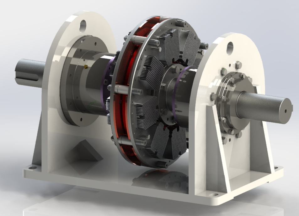
The permanent magnet speed regulator transmits torque by adjusting the mutual magnetic coupling between the guide magnet and the permanent magnet, while achieving load speed regulation and motor energy conservation. It is a soft start device without mechanical connection, with a transmission efficiency of over 95% and a motor energy saving of over 30%. The main application equipment is pumps, fans, centrifugal loads, belt conveyors, and other mechanical devices, which are widely used.

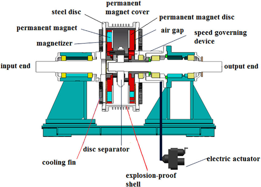
The permanent magnet speed regulator adjusts the load speed by adjusting the effective area of the permanent magnet magnetic coupling (cylindrical) or the gap of the permanent magnet magnetic coupling (disc), while keeping the motor speed unchanged, achieving load speed regulation and motor energy conservation. The speed regulation mechanism adjusts the relative coupling area between the cylindrical permanent magnet rotor and the cylindrical conductor rotor in the axis direction, or adjusts the relative clearance between the disc type permanent magnet rotor and the disc type conductor rotor in the axis direction, in order to change the magnitude of torque transmission between the conductor rotor and the permanent magnet rotor. The conductor rotor is installed on the input shaft, and the permanent magnet rotor is installed on the output shaft. When the conductor rotor rotates, the conductor rotor and the permanent magnet rotor generate relative motion, and the permanent magnetic field generates eddy currents on the conductor rotor. At the same time, the eddy currents generate induced magnetic fields and interact with the permanent magnetic field, driving the permanent magnet rotor to rotate in the same direction as the conductor rotor. As a result, the torque of the input shaft is transmitted to the output shaft; The magnitude of output torque is related to the area of interaction (or the gap between interactions). The larger the area of interaction (or the gap between interactions), the greater the torque and the higher the load speed. Conversely, the opposite is true. The permanent magnet rotor is completely disconnected from the conductor rotor, with zero action area (or maximum action gap), and the permanent magnet rotor speed is zero, that is, the load speed is zero. Can achieve repeatable, adjustable, and controllable output torque and speed. The permanent magnet governor achieves speed control by adjusting torque. The torque output from the motor to the permanent magnet governor is equal to the torque output from the permanent magnet governor to the load. When the permanent magnet governor receives a control signal, such as pressure, water flow rate, liquid level height, etc., it is transmitted to the speed control mechanism of the permanent magnet governor. After identifying and converting the signal, the speed control mechanism generates a mechanical operation command to adjust the coupling area between the conductor rotor and the permanent magnet rotor (cylindrical), or the coupling gap between the conductor rotor and the permanent magnet rotor (disc), according to the requirements of timely load input torque, Adjust the torque at the input end of the permanent magnet governor. The load requires a small torque, the motor output torque is small, and the corresponding motor output power is also small. To ultimately change the output power of the motor, achieve energy-saving and improve the working efficiency of the motor.

The permanent magnet governor mainly consists of four components:
Permanent magnet rotor: An aluminum disk embedded with a permanent magnet (strong rare earth magnet), connected to the load shaft.
Magnetic rotor: Magnetic disk (copper or aluminum), connected to the motor shaft
Air gap actuator: Adjust the air gap mechanism between the disk and the guide disk
Connection mechanism: The tightening disc device is connected to the motor shaft.
Permanent magnet governor | Frequency converter |
Smooth stepless speed regulation, with a speed range of 0-98%, achieving high efficiency and energy conservation, with a power saving rate of 10-50%. | The frequency converter cannot operate at low speed. |
Simple, reliable, mechanical structure, no need for external power supply. | The frequency converter has a complex structure and is a pure electrical and electronic device. |
Isolate vibration without mechanical connection. | The adaptability and maintainability in harsh working environments are not possessed by frequency converters. |
Easy to install, tolerating large alignment errors, and occupying small space; | The frequency converter requires large installation space and high environmental requirements (relatively dust-free space). |
Flexible starting reduces the impact current of the motor and extends the service life of the equipment. | When the voltage drops, the frequency converter may not work, but the permanent magnet governor is not affected. At low speeds, the frequency converter reduces the speed of the motor while also reducing the efficiency of the cooling fan, which may cause the motor to overheat, while the permanent magnet governor does not have this problem. |
Capable of adapting to various harsh environments, including places with high voltage fluctuations in the power grid, severe harmonics, flammability, explosion, humidity, dust, etc, | Frequency converters cannot be used in various harsh environments, including places with high voltage fluctuations in the power grid, severe harmonics, flammability, explosion, humidity, dust, and other environmental conditions. If there is a problem, it will cause all shutdowns. |
Extend the service life of the main components of the transmission system (bearings, seals, etc.) and reduce maintenance costs. | The frequency converter does not have this function. |
Green environmental protection, no harmonics, no pollutants, and no EMI (electromagnetic wave) interference issues. | Frequency converters produce harmonics and pollute the power grid. |
Long service life, up to 20 to 30 years. | The service life of the frequency converter is about 8 years, and as the service life increases, the failure rate increases year by year. |
The maintenance workload of the permanent magnet governor is minimal, and the operating cost is low. | The operation and maintenance costs of frequency converters are high, and accessories are expensive, making maintenance difficult. |
Permanent magnet speed regulators can be widely used in industries such as power generation, metallurgy, petrochemicals, water treatment, mining and cement, pulp and paper, HVAC, shipbuilding, irrigation, etc. In the above-mentioned industries, the application equipment includes pumps, fans, centrifugal loads, bulk cargo handling, belt conveyors, and other mechanical devices, with a very broad application prospect. The permanent magnet speed regulator can easily retrofit existing equipment without the need for any modifications to the existing motor and power supply. In most cases, shutting down or removing existing process control hardware devices is sufficient. The load will operate at the optimal speed, improving energy efficiency, and reducing operating and maintenance costs.
Contact: Cindy Wang
Phone: +86 19916725892
Tel: 0512-55128901
Email: [email protected]
Add: No.6 Huxiang Road, Kunshan development Zone, JiangsuShanghai Branch: No. 398 Guiyang Rd, Yangpu District, Shanghai, China