Two-material powder injection molding (PIM) or two-color PIM (2C-PIM) has its basis in the more prevalent 2C-PIM of plastics. An extension of PIM, 2C-PIM is viewed and investigated as a technology to manufacture near-net-shaped, functionally graded composites combined with the shape complexity that can be realized via PIM. Since then, the concept and evaluation of 2C-PIM has been applied to numerous material systems with a variety of potential applications ranging from the size and shape complexity of a typical PIM part to Micro-PIM parts.
As with the PIM process, 2C-PIM starts with the preparation and rheological characterization of feedstock, followed by injection molding to form a green component. Molding of the components can be accomplished by overmolding and coinjection molding. In the overmolding variant, a molding machine that is equipped with two injection units is typically used to inject two different polymer/metal powder mixtures or compounds into the desired shape. The molded part composed of two different materials is thermally processed to remove the polymer and sintered to yield a single, integrated component. A schematic diagram of the injection molding step of this process is shown in Fig. 16.1. The concept is first to mold one part in a cavity and then rotate the tooling to form another cavity and mold around the already molded part. The component is then composed of two interlocked materials and is ejected from the mold. This is typically a manual process, where first the component is molded, cooled to room temperature, and then transferred to another mold followed by overmolding, but this is best achieved using a twin-barrel injection molding unit. Typically, overmolding is used to evaluate the process feasibility and make prototypes.
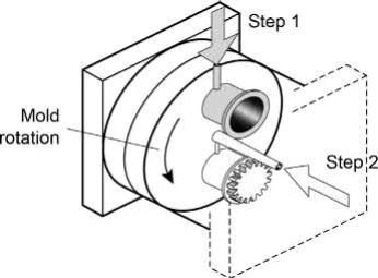
Fig. 16.1 Schematic diagram of 2C-PIM process via overmolding
In coinjection molding, a functionally graded structure is produced using the flow behavior of the materials, through the same runner system, to produce a structured component that has a core and skin of two different materials. This is a well-established technology for plastics and has beenexperimentally examined fortwometal powders. Coinjectionmolding machines are equipped with one-, two-, or three-channel systems. In the one-channel system, the feedstock is introduced sequentially into the mold by shifting a valve, as shown schematically in Fig. 16.2A. Owing to the fluid flow characteristics, the first feedstock adheres to the cooler mold surface, forming a skin. Thickness of this skin is controlled by the injection rate, temperature and to some extent the flow compatibility of the two materials. In a two-channel system, Fig. 16.2B, it is possible to inject two feedstocks sequentially or simultaneously. For plastics, profile injection is preferred as it provides enhanced control of the surface appearance. A three-channel system allows for simultaneous injection with a direct sprue gate, Fig. 16.2C. Typically, the skin thickness is influenced on both sides of the part. Fig. 16.3 illustrates the cross-sectional differences between overmolding and coinjection molding.

Fig. 16.2 Schematic diagram of runner system and molding in (A) one-channel, (B) twochannel, and (C) three-channel coinjection molding
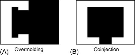
Fig. 16.3 Schematic diagram of the cross-sectional difference between 2C-PIM via (A) overmolding and (B) coinjection molding
There are no known challenges to forming green parts via overmolding that are very specific to 2C-PIM. Rheological characterization and mold filling operations are a direct extension from the typical PIM cases. Different feedstock systems such as wax polymerbased, Catamold-based or water-based feedstocks are used successfully.
It has been largely recognized from early stages of development that the two materials should exhibit or be tailored to exhibit similar densification behavior to avoid defect formation. This aspect of 2C-PIM is by far the most challenging and will ultimately make the design and the product either successful or unviable.
During thermal processing, the injection molded part undergoes various changes and as a consequence assumes the character of material with different thermomechanical characteristics. The polymer softens, disintegrates and burns off in the temperature range of 200-500℃, resultingin a highly porous and fragile brown part. For atypical powder characteristics of D50 of 5-10 for metals and about 0.2-0.5 for ceramics used in PIM, the particle sizeistoolargeto exhibit any significantinitial stage sintering during debinding.The brown part maintains its integrity due to interparticle friction. The strength of the brown part after debinding and before the onset of initial stage sintering is typically less than 1MPa. At this stage, the mechanical behavior is similar to a very brittle material and differencesinthethermal expansion or degradation characteristics ofthe binders arelikelyto have alargeimpact. Typically,thetwo materials utilizethe same binder system and, other than small dilation duetothermal expansion, one can expect an absence of relativemotion between the two components during this stage. The part is expected to survive this stage without generating any defects.
Strength increases with the onset of neck growth. With a further increase in temperature and the ensuing densification, the stresses in the components and the assembly gain importance due to differences in sintering shrinkage. Porosity during the initial stage of sintering is approximately 30-45vol%. Owing to porosity, the material continues to behave like a brittle material but with increasing plasticity with an increase in temperature. Defects formed during this stage include delamination of the interface or channeling cracks through the thickness of the component, largely attributable to the differential shrinkage and the ensuing stress state.
With the onset of the second stage of sintering, thermal softening lowers the strength and increases the plasticity of the material. It is conceivable that the differences in shrinkage behavior can be tolerated to a higher degree during the second and the final stage of sintering. In case of liquid phase sintering, experiments suggest that these tolerances are even higher with the possibility that any defects formed are effectively healed.
As mentioned earlier, success of 2C-PIM depends on minimizing the differences in shrinkage during sintering. This would occur naturally in very few material systems-systems with similar compositions and particle size distribution. For dissimilar materials, parameters that can be availed to match the sintering characteristics include a choice of material system, powder particle size, and powder volume fraction in the feedstock.
For metallurgically compatible systems, defects can be avoided if the intrinsic strength of the material exceeds the stresses induced. Induced stresses are a strong function of component geometry and the extent of shrinkage mismatch. Qualitative measures such as the Apparent CoSintering Index can be used as a rapid screener for 2C-PIM, but such measures restrict the choice of material without any consideration to the component design. Mapping the process window for 2C-PIM involves four distinct information streams.
Difference in the sintering shrinkage with temperature: difference in shrinkage during sintering is essential to understand and develop products that utilize 2C-PIM technology. Dilatometry is a very useful tool in understanding and providing a quantitative measure of material compatibility. Dilatometry curves for the materials under consideration can quickly validate the merits of 2C-PIM. Fig. 16.4A-D compares the shrinkage behavior of M2 tool steel with Fe-10Cr-0.5N and 316L SS + 0.5B to illustrate the impact of difference in shrinkage behavior and the importance of dilatometry.
In situ strength of material: in situ strength of the PIM component changes during different stages of processing. This plays an important role in the ability of the material to withstand stresses caused by difference in the sintering shrinkage. Strength of specific material can be experimentally determined by high-temperature mechanical testing. However, an approximate value will suffice during the design and proof-of-concept stage and can be obtained by simple models. These models are found to be in general agreement with the experimental results. Variation in the in situ strength of a powder compact is a function of its material properties, particle size, relative density of the compact, and the neck size.
Thermomechanical behavior: choice of the correct thermomechanical behavior is important to model the induced stresses. These models can range from simple elastic to elastoplastic and visco-plastic models. To predict the success of 2C-PIM geometry, an elastic model can provide a conservative estimate. These models should consider the reduction in the strength of the material due to porosity and the temperature effects.
Stress state: difference in sintering shrinkage does not necessarily indicate material incompatibility toward 2C-PIM. The stress state of the final geometry is far more important. Despite differences in sintering shrinkage, component geometry can be designed to withstand or lower the induced stress. Simple geometries can use closed-form solutions such as radial stress and hoop stress for circular cross-sections in either plane stress or plane strain conditions and can prove very useful in understanding the effect of different geometries. Fig. 16.5 shows the impact of difference in sintering shrinkage and metallurgical compatibility on the success of 2C-PIM. An increase in shape complexity warrants the use of finite element method models to understand the stresses induced during sintering.
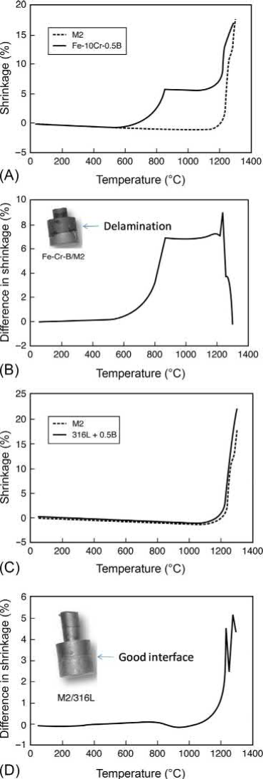
Fig. 16.4 Parts (A) and (C) are dilatometer results showing shrinkage of M2 tool steel with Fe-Cr-B and 316LS +B. Parts (B) and (D) show the difference in shrinkage (mismatch) and its effect on the success or failure of 2C-PIM
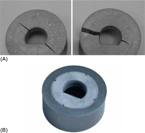
Fig. 16.5 Pictures of components with varying densification characteristics to induce and illustrate the defects during 2C-PIM: (A) cracking due to hoop stress initiated by excess shrinkage of the inner core (left) and outer core (right) and (B) delamination and poor bonding at the interface between metallurgically incompatible systems
Fig. 16.6 shows a few prototypes made via 2C-PIM. Successful prototypes made using 2C-PIM technology include a holder for angle-of-rotation sensors used in automotives, tool steel inserts with stainless steel core, hermetic microelectronic packages with embedded heat sinks , microinjection molded ceramic resistive heater elements, and microshaft and gear assemblies. The technology is also demonstrated on a variety of material systems and applications. For instance, copper-based heat sinks with porous channels acting as heat pipes, graded WC-Co composites, 17-4PH/316 L, Inconel 718/Inconel 625, M2/316 L, and porosity-graded Co-Cr-Mo alloy and Al/Fe-Nd-B, Al2O3/TiN, Al2O3/ZrO2, and 3Y-TZP/stainless steel. Case studies for some of the previously mentioned combinations are detailed by Petzoldt. Layered composites similar to low-temperature cofired ceramics (LTCCs) or hightemperature cofired ceramics (HTCCs) are excluded as they are not injection molded. While the challenges in sintering defect-free LTCC and HTCC components exist and are similar to 2C-PIM, there is also a possibility of using external uniaxial pressure during sintering to alter the shrinkage and densification characteristics.
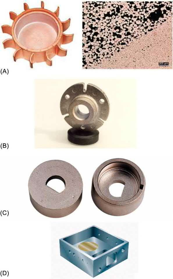
Fig. 16.6 Pictures and schematic diagrams of a few prototypes explored via 2C-PIM: (A) copper-based heat sink with porous structure to act as heat pipe. (B) and (C) automotive sensor holders. (D) Housing for hermetically sealed electronic package with embedded heat sink.
PIM provides the geometric shape attributes associated with plastic injection molding and the performance attributes associated with full-density powder metallurgy and ceramic sintering. The technology excels in the mass production of complicated shapes from materials that are difficult to cast or machine. PIM continues to see impressive gains in the production but also continues to be restricted to monolithic materials.
Since the initial study on 2C-PIM in 1992, there have been less than 50 unique technical articles on the subject and less than 10 patents applied that utilize this method of forming. To the knowledge of the author, there have been a few prototypes manufactured to make functional material via 2C-PIM but there are no products with production volumes that can be realized by PIM.
2C-PIM aims to provide multifunctionality to the components by combining the near-net-shape manufacturability of PIM with the cost savings. Cost saving is largely realized by reducing the secondary joining operations. Success of two-color plastic injection molding is derived by functionality and economics. On the other hand, 2C-PIM is yet to mimic this success. PIM competes with other forming technologies such as die casting, investment casting, and machining. To derive the competitive advantage, a successful PIM product has specific characteristics, operating within a range of component weight, shape complexity and production volume. 2C-PIM narrows down this window further owing to the constraints imposed to make a defect-free component along with other competitive joining technologies such as laser brazing, electron beam welding, and fusion brazing.
Evolution of this technology to provide multifunctionality is yet to be realized. It is likely that the initial focus on reducing cost is not the appropriate strategy for 2C-PIM. Competing joining technologies, where available, are relatively mature, minimizing the incentive to investigate and develop products that yield defect-free components. While large-scale adoption is yet to be realized, it is likely to come from a combination of material systems that can only be processed via powder routes and have sufficient geometric complexity so that they cannot be processed via the press-and-sinter technique or joined by way of brazing or diffusional bonding. Similar to the ability of PIM technology to make products whose properties meet or exceed the wrought properties of equivalent material, the interfacial strength of a successful 2C-PIM product is likely to be superior to alternative joining technologies. 2C-PIM will likely find its success in niche applications, adding significant value to the component, and not as a highly productive, cost competitive technological alternative. Adoption of this technology will also require a greater integration of the design and stress analysis of the component to generate a defect-free component and provide the benefit of multifunctionality.
Contact: Cindy Wang
Phone: +86 19916725892
Tel: 0512-55128901
Email: [email protected]
Add: No.6 Huxiang Road, Kunshan development Zone, JiangsuShanghai Branch: No. 398 Guiyang Rd, Yangpu District, Shanghai, China