The introduction of new processing routes such as MIM for aero engine components requires an extensive material and process validation to assure high and reproducible material quality. Accordingly, mechanical testing including tensile testing, fatigue testing, and creep testing is essential. However, only few fatigue and creep test data are published so far in the field of injection molded nickel-base superalloys. The following section gives an overview on reported mechanical test data for injection molded nickel-base superalloys.
Tensile properties are mostly determined at room temperature. However, in recent years different research groups have tested different types of alloys also at elevated temperatures and could achieve promising results comparable to cast or wrought reference alloys. The 0.2% yield strength, the UTS and the elongation at fracture determined by different research groups for MIM IN 718 and MIM IN 713 for different temperatures is shown in Fig. 24.8 and 24.9. Cast and wrought reference data are also plotted as comparison.
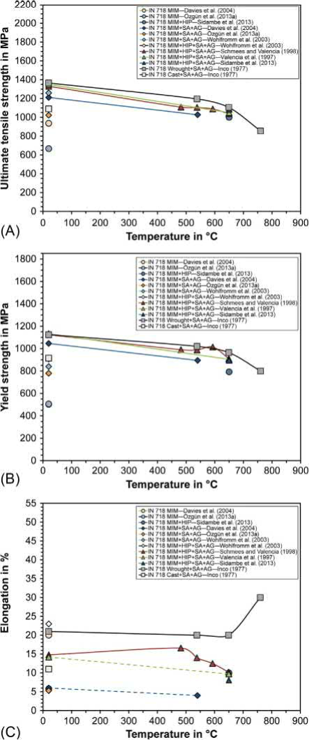
Fig. 24.8 (A) Ultimate tensile strength. (B) 0.2% yield strength. (C) Elongation at fracture of MIM IN 718 determined by different research groups in comparison to tensile properties of wrought and cast reference material for different temperatures.
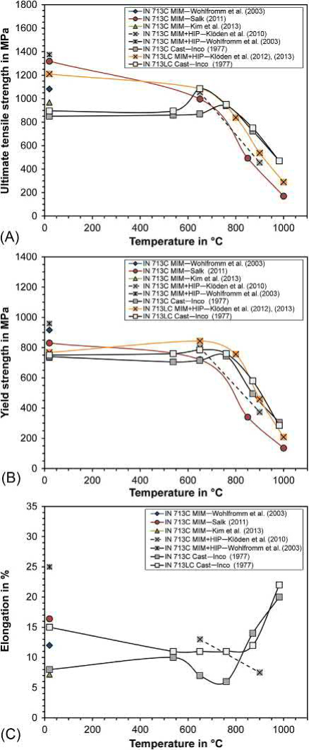
Fig. 24.9 (A) Ultimate tensile strength. (B) 0.2% yield strength. (C) Elongation at fracture of MIM IN 713 determined by different research groups in comparison to tensile properties of cast reference material for different temperatures.
Table 24.2 gives an overview on reported tensile properties for different nickelbase superalloys in different conditions (as-sintered, sintered and heat-treated, sintered and hot isostatically pressed, sintered and hot isostatically pressed and heattreated). However, it has to be noted that different sample geometries and test speeds have been used. Especially the ductility is affected by the sample geometry and might differ for different test specimen geometries. Moreover, the densities and the impurity contents differ for different alloys and research groups. Also the chemical composition of the alloys might differ slightly.
For MIM nickel-base superalloys, the only available material standard is AMS 5917 for MIM IN 718. Thus, there is a lot of work to be done in order to establish similar standards also for other nickel-base superalloys fabricated by MIM.
For several aerospace applications, high cycle fatigue (HCF), and/or low cycle fatigue (LCF) properties are of main interest. Published information is available mainly for IN 718 and IN 713LC. For heat-treated metal injection molded IN 718, an approx. 30% reduced fatigue endurance limit at 538℃ compared to wrought IN 718 material is reported. The room temperature rotating bending fatigue limit of MIM IN 718 with 98%-99% theoretical density obtained was 65% of the fatigue limit of wrought alloy. In both investigations, residual porosity is assumed to reduce the fatigue strength of injection molded material. A research group from IHI Corporation however, reported MIM IN 718 hightemperature fatigue strengths higher than for wrought material. In order to simulate the influence of microporosity, an artificial defect of 0.1mm diameter was introduced in some test samples. The 0.1mm surface defects did not lead to any drop of the fatigue strength.
Investigated the high cycle fatigue behavior at 650℃ of MIM IN 718 material that was hot isostatically pressed (1190℃/104MPa/4 h) and subsequently heat-treated per AMS 5663. The results obtained at an R ratio of -1 indicated a higher fatigue life for metal injection molded material than the AMS 5596 minimum requirements. A fatigue stress of 448MPa at 107 cycles was determined which is 37% above the AMS 5596 minimum requirement (327 MPa).
Another MIM nickel-base superalloy that was investigated with regard to fatigue properties is IN 713LC. Rotating bending fatigue testing of MIM IN 713LC at 500℃ reveals significantly better fatigue properties of MIM IN 713LC material compared to cast and hot isostatically pressed IN 713LC alloy.
These examples show that for metal injection molded nickel-base superalloys, fatigue properties sufficient for practical applications can be achieved. The good fatigue properties for MIM nickel-base superalloys can be explained by the fine grained microstructure obtained via MIM. Elimination of γ-γ'-eutectics and refractory segregation compared to castings may also play a role in certain cases.
For high-temperature applications, creep deformation has to be considered and is thus of interest for material selection. Information on creep performance of metal injection molded nickel-base superalloys is mainly available for IN 718, IN 713LC, CM 247 LC, and Udimet 700.
For metal injection, molded Udimet 700 creep strength comparable to cast material is reported. Investigated the stress rupture properties of metal injection molded IN 718. It was shown that powder injection molded, hot isostatically pressed and δ-phase optimized heat-treated (870℃/10 h + heat treatment per AMS 5663 specification) material meets AMS 5596 requirements. For 650℃ test temperature and 689.5MPa load, time to rupture of 35.9± 0.62 h and final elongation of 5.4±1% are reported.
The creep resistance of injection molded IN 713LC is lower compared to cast and hot isostatically pressed IN 713LC. A heat treatment consisting of solution annealing followed by an aging step leads to somewhat improved creep resistance. Similar results have been observed for injection molded CM 247 LC: creep properties of MIM material are inferior to cast and HIPed material, but can be improved by a solution and two step aging heat treatment.
However, creep strength in the range of cast alloy cannot be reached due to the fine grained microstructure (ASTM 8-10) after MIM. For further improvement of creep resistance, coarser microstructure would be required.
The development of superalloy parts fabricated by MIM is mainly driven by the aerospace sector. Cost reduction is the main driving force as MIM is a promising technology to meet cost saving targets. With MIM IN 718 parts for gas turbine engine hardware, the cost reduction compared to machining of wrought material is >50%. Development, testing and validation have progressed significantly. Strong evidence for this is an increasing number of research publications and patents in this field. However, only few test data are published due to the fact that the research efforts are mainly financed by each company individually and thus will be kept confidential. Nevertheless, some examples for developments are mentioned in literature and on conferences. Unfortunately, in most cases no information is available if the technical readiness level has been achieved and if the product is in production or in service. Suitable are small to medium-sized complex parts with large production volumes (>10,000 annually). However, critical production volumes to achieve cost saving in the aerospace sector can be much smaller than in automotive industry due to greater geometric complexity and higher part prices for conventional manufacturing routes. Additionally, in aerospace, engine parts are required for many years as systems are in service for several decades, i.e., the numbers accumulate over the years. With regard to part size and numbers high pressure compressor parts and small turbine parts like compressor vanes and retaining plates appear best suited for MIM.
Within a MIM development program of MTU Aero Engines AG compressor vanes could be produced with high-dimensional quality and low surface roughness. By brazing four vanes, vane clusters were obtained. These vane cluster prototypes were qualified for engine testing after successive brazing of a conventional honeycomb seal onto the inner shroud (see Fig. 24.10) .
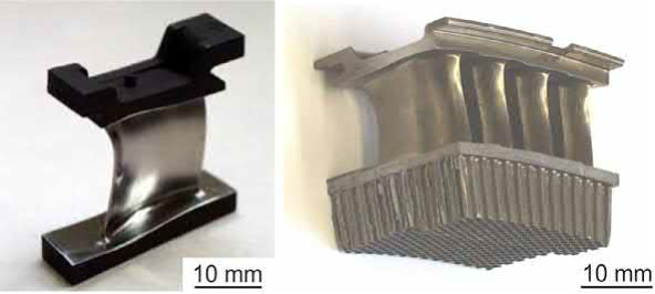
Fig. 24.10 Single MIM compressor vane (left) and MIM vane cluster prototype for engine testing (right)
Another application for MIM parts that has been investigated by MTU are honeycomb seals for turbines. Accordingly, the alloys IN 713C and Mar-M247 have been the focus of research. This potential application is also subject of a patent application, which describes that the honeycomb seal is composed preferably of several segments. Each segment is embodied as a single piece and has a base element as well as honeycomb elements that are embodied as a single piece with the base element (patent US 20090041610 A1).
Rolls-Royce reported on MIM as alternative manufacturing route to replace forged IN 718 compressor stator vanes (PIM, 2011). Stator vanes produced by MIM using polymethylmethacrylate (PMMA) and a water soluble polymer as binder components have been investigated. As reported, tolerances of ±0.5% can be achieved. A single forging stage followed by a finishing process is applied to obtain desired dimensional and surface quality.
More recently, large volume parts like compressor vanes, dampers, dowels, washers, lockplates, and sleeves were listed as potential candidates for MIM for aero-engines (Daenicke, 2017). Typical large volumes in the aero engine sector are in the range of an annual demand of approximately 1000-100,000. As pointed out earlier, the contract times are usually significantly longer compared to other industries, resulting in relatively large accumulated numbers. A typical compressor vane as candidate for MIM is shown in Fig. 24.11.
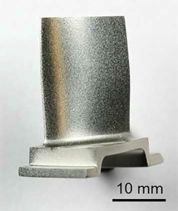
Fig. 24.11 High pressure compressor vane produced via MIM
The current solution for manufacturing this part consists of extrusion, machining, and brazing steps. The metal injection molded fuel nozzle is built up from four subparts that are injection molded separately, machined in the green state, assembled as green parts, debound, and sintered. The as-sintered parts are heat-treated to achieve the required material properties and finally machined. The assembled fuel nozzle is shown in Fig. 24.12.
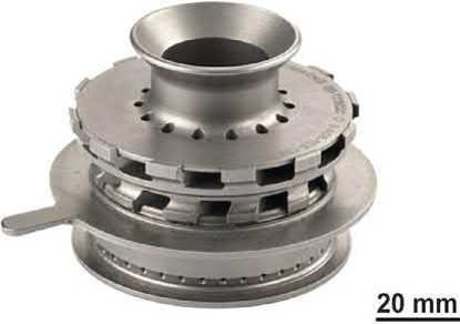
Fig. 24.12 Aero engine fuel nozzle from Hastelloy X produced via MIM. Courtesy of Safran Aircraft Engines and Alliance-MIM
MIM was able to provide a high-dimensional stability, very good metallurgical quality, and good mechanical properties. Thus, the metal injection molded fuel nozzle has been successfully validated as alternative technology for one of Safrans's development engines. This investigation took 3 years, including process setting and validation as well as supply-chain upgrading showing that the investigation of superalloy MIM components is an intensive development process.
The IHI Group, which is a major supplier to General Electric's GE-90 engine used on Boeing's 777 passenger jets, as well as to the GEnX engine used on Boeing's Dreamliner, published results on the development of Alloy 718 compressor vanes. Sufficient fatigue strength and material strength was obtained for high pressure compressor applications. Complex compressor vane prototypes could be manufactured using a newly developed deformation-resistant binder system.
Another important sector interested in nickel-base superalloy MIM parts besides the aerospace industry is the automotive industry. Nickel-base superalloy components in the focus of interest for fabrication by MIM are turbocharger components. An example of a turbocharger wheel prototype manufactured by Schunk Sintermetalltechnik GmbH is shown in Fig. 24.13.
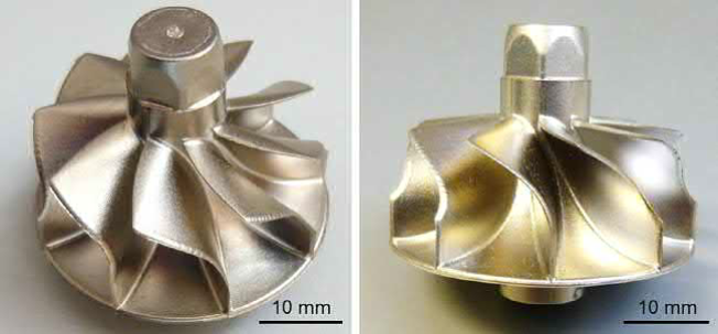
Fig. 24.13 IN 713LC turbocharger wheel prototype produced by metal injection molding
For this application, materials with good oxidation and corrosion resistance as well as excellent mechanical properties are required since the turbine wheel is driven by the engine's exhaust gases. Nickel-base superalloys meet these requirements. Traditional turbocharger turbine wheels are manufactured by investment casting. MIM would be an interesting cost-efficient alternative manufacturing route. However, no evidence about MIM turbocharger wheels currently in use is available.
Thus, it can be summarized that many research activities on MIM of superalloys are ongoing in aerospace and automotive sector. This is also proven by several patents and patent applications on MIM of superalloys by, e.g., BASF (e.g., patent EP 2416910 A1), MTU Aero Engines (e.g., patent DE102004060023 B4, DE102004057360 B4). However, published data and information about parts in service are quite rare.
MIM of superalloys is generally comparable to other types of MIM materials such as steels. In several studies during the last 30 years, it was shown that nickel-base superalloys can be processed successfully via MIM and sintered to a relative density of >98% with moderate pick up of impurities like carbon and oxygen.
Tensile properties of MIM material at low and intermediate temperatures are often comparable to cast or forged material. Unfortunately, ductility and creep resistance at high temperatures are often inferior for MIM, probably due to the existence of coarser precipitates/inclusions, remaining pores, PPB, and small grain size, respectively. Heat treatments or HIP with parameters known from cast or wrought materials can be used to close pores, alter the microstructure, and improve the mechanical properties.
Unfortunately, generally only few data are available on relevant high-temperature mechanical properties as material characterization and validation times are long, expensive, and confident. According to the number of references, IN 718 has been studied the most, followed by IN 625 and IN 713. Much more data would be necessary in order to assess the application potential of different MIM nickel-base superalloys. Also an increased number of material standards would help to introduce MIM of nickel-base superalloys for a broader market and would minimize the individual development effort for interested companies.
Some main challenges for the future are a better control of impurities in the MIM process, assuring microstructure and property repeatability and a robust supply chain. With regard to the chemical composition, up to now mainly alloys that have been developed for forging or casting were used for MIM. Alloy development programs designing specific MIM superalloys that take advantage of the rapid solidification in fine powders could help to improve the material performance.
Contact: Cindy Wang
Phone: +86 19916725892
Tel: 0512-55128901
Email: [email protected]
Add: No.6 Huxiang Road, Kunshan development Zone, JiangsuShanghai Branch: No. 398 Guiyang Rd, Yangpu District, Shanghai, China