Tool steels are a family of steels that contain dispersed carbides in a hardened steel matrix. These steels are used in metal-cutting, tool and die, and many other hot and cold wear applications. The carbides typically present in these steels are vanadium-rich MC type, W- and Mo-rich M6C type, and depending on the alloy composition, Mo-rich M2C, and chromium-rich M23C6 type. The MC carbides are the most wear resistant of all. The M23C6 carbides precipitate at lower temperatures, and during heat treatment. Heat treatment includes austenitizing and quenching, similar to traditional steel; however, because of the high carbon content, retained austenite is present after the quench. Austenitizing is done near the solidus temperature, where all of the M23C6 and most of the M6C are taken into solution. Usually two tempering operations are performed. The first operation tempers the martensite formed from the first quenching, and also precipitates M6C and M23C6 carbides. This depletes the retained austenite of carbon, allowing it to transform to martensite during cooling. The second tempering operation will temper the newly formed martensite.
Traditionally, tool steels were ingot cast, which results in segregation of alloying elements during solidification and large carbide precipitates that form stringers upon hot working. In the 1960s, hot isostatic pressing (HIP) of large, spherical-shaped, gasatomized tool steel powders to full density was developed. The HIPed billet is hot worked into various near-net shapes. This method avoids the segregation inherent to casting and, owing to the small precipitate size in the powders, results in a finer microstructure with well-dispersed carbides. As a result of the refinement of the microstructure, HIP tool steel will possess higher toughness and similar hardness compared to an ingot cast tool steel of the same composition. The development of the HIP process also gave way to development of higher alloyed tool steels such as CPM10V (AISI A11) and CPM9V (lower carbon and vanadium content version of AISI A11) that could not be cast.
Cold compacted and sintered water-atomized powders were demonstrated for several tool steel grades in the 1980s and early 1990s, allowing increased net shaping ability over HIP high-speed tool steels with microstructure and performance similar to HIP-hot worked tool steels. Powder injection molding (PIM) of tool steels followed in the late 1990s, allowing for further increased shaping ability. PIM tool steels can utilize the fine cuts (-325 mesh, -400 mesh) of the gas-atomized powders, which are not desirable for HIP. Common PIM high-speed tool steel grades are M2, M4, T15, and M42. Metal injection molding (MIM) tool steel components find application in medium- to high-volume wear applications-such as cutting bits, crimping jaws, and other tooling components. For an example, MIM high-speed tool steel cutting bit application is shown in Fig. 22.1. Other tool steel grades such as A2 and S7 are in MIM production; however, their processing is different from high-speed tool steels and more closely matched to low alloy steels since their alloy content is lower than the high-speed tool steels.
In this section, a review of the MIM process is presented in the context of processing of high-speed tool steels. Where applicable a comparison with other MIM processing concerns is presented.
Owing to a spherical shape and size similar to stainless steel powders, feedstock formulation, and injection molding of gas-atomized high-speed tool powders are very similar to that of 316L and 17-4PH stainless steel. Typical powder properties of a few high-speed tool steel powders are given in Table 22.1. The stoichiometry of a few high-speed steels is given in Table 22.2.
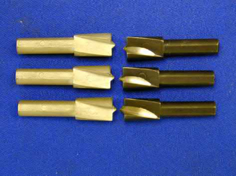
Fig. 22.1 MIM high-speed steel cutting bits. Components on the left are as molded and the components on the right are heat treated, black-oxided, and ground sharpened
Table 22.1 Typical D90<22μm gas-atomized high-speed tool steel powder characteristics
Powder size distribution (μm) | ||||
Alloy | D10 | D50 | D90 | Pycnometer density (g/cm3) |
M2 M4 T15 M42 | 5.7 7.8 7.8 8.2 | 11.2 14.2 10.7 15.7 | 18.6 22.8 18.3 23.6 | 8.02 8.02 8.18 8.02 |
Table 22.2 Typical stoichiometry of a few high-speed tool steels
Alloy | C | Mn | Si | S | P | Cr | W | V | Ni | Mo | Co | Cu | Fe |
M2 | 0.80 | 0.18 | 0.02 | 4.10 | 6.08 | 1.93 | 5.16 | Bal. | |||||
M4 | 1.43 | 0.41 | 0.42 | 0.13 | 0.016 | 4.42 | 5.69 | 3.9 | 0.21 | 4.5 | 0.39 | 0.10 | Bal. |
T15 | 1.53 | 0.19 | 0.21 | 0.11 | 4.2 | 12.0 | 4.6 | 0.32 | 4.8 | Bal. | |||
M42 | 1.13 | 0.23 | 0.6 | 0.08 | 0.019 | 3.8 | 1.46 | 1.15 | 0.31 | 9.5 | 7.98 | 0.10 | Bal. |
Wax-polymer and polyacetal based binders have been demonstrated and are commercially available as premixed feedstock. Solids loading is typically 60-67 vol.% for gas-atomized powder, and 51-63 vol.% for water-atomized powder, depending on the powder size distribution and binder formulation.
Tool steels such as A2 and S7 have feedstock processing similar to the alloy steels, such as 4140 or 4605, where the base material is a carbonyl iron powder and the alloying additions are in the form of elemental additions or master alloys.
Debinding of PIM tool steels presents some challenges in carbon control. Pure H2 atmosphere results in decarburization, while N2 or Ar atmospheres can result in carbon pick-up from incomplete binder burn-off, or carbon loss from reaction with oxygen in the powder or atmosphere. A mixture of 5%-25% H2/balance N2 is often used; however, CO/CO2 or CH4/H2 blends may also be used during presintering for more precise control of carbon. Debind temperatures depend upon the temperature at which the polymer burns out in the atmosphere of interest. Thermogravimetric analysis (TGA) of the as-molded material should be performed in the atmosphere of interest to determine the proper temperature to ensure the polymer is burned out properly and not too quickly. When a polymer is burned out too quickly, it leaves carbon residue, which can drastically affect the sintering response and subsequent mechanical properties.
Sintering of PIM tool steels is achieved by supersolidus liquid-phase sintering. In prealloyed powders, liquid is formed on the grain boundaries and between particles upon heating above the solidus temperature. When a critical coverage of the grain boundaries with liquid is reached, rapid densification to near 100% density occurs. Densification may occur within as little as 10 min. This rapid densification can be clearly seen using dilatometry. A dilatometer plot of M2 tool steel is given in Fig. 22.2. Notice that little densification occurs until about 1250℃, where rapid densification occurs. This rapid densification is due to liquid formation at the grain boundaries. Too much liquid coverage of the grain boundaries will lead to distortion. During supersolidus liquid-phase sintering, grain growth is very rapid, so grain boundary area is constantly decreasing. This means that even though the liquid volume fraction may be constant once the sintering hold begins, the fraction of coverage of grain boundaries with liquid will increase during the hold time, possibly resulting in distortion.
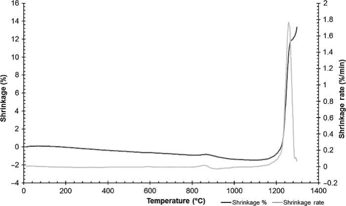
Fig. 22.2 Dilatometer plot of M2 tool steel, showing rapid densification at 1250℃
For tool steels, microstructural problems typically precede significant distortion. M6C carbides form a eutectic liquid with the steel matrix during sintering. Upon cooling, excessive liquid pools from oversintering will solidify into grain boundary carbide films or lamellar mixtures of carbide and steel, rather than discrete carbide particles. These films and lamellar structures will degrade mechanical properties by creating an easy crack propagation path along the grain boundaries. Properly sintered tool steel will precipitate discrete carbides on the prior austenite grain boundaries upon cooling. Fig. 22.3 shows undersintered, properly sintered, and oversintered M2 tool steel. The "sintering window" is the allowable variation in temperature and time that will produce an acceptable density without unacceptable microstructural coarsening or distortion. Usually, for a given time, the allowable temperature variation is less than 50℃, but may be as low as 5℃. This sintering window is dictated by thermodynamics and can be illustrated by a pseudobinary-phase diagram. For an example, pseudobinary-phase diagram is shown in Fig. 22.4 for M2. The sintering window can be approximated by the temperature range of the liquid + austenite + carbide-phase region at the carbon content of M2, which is approximately 0.85%. The temperature range at this carbon content is only 13℃, from approximately 1245-1258℃. Tight temperature control and short hold times are preferred for optimal processing. Highly accurate sintering control can be obtained by using well-tuned multi-zone sintering furnaces.
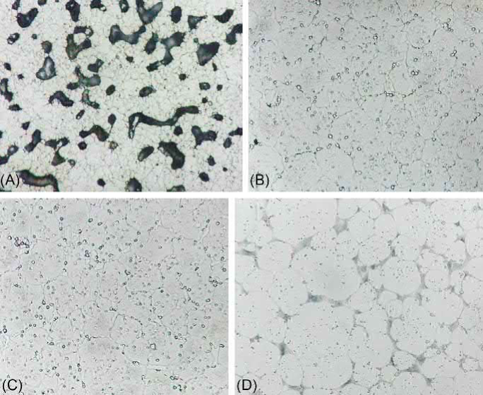
Fig. 22.3 M2 tool steel: (A) Undersintered. (B) Properly sintered. (C) Slightly oversintered, with discontinuous grain boundary carbide films. (D) Overintered, with lamellar structure
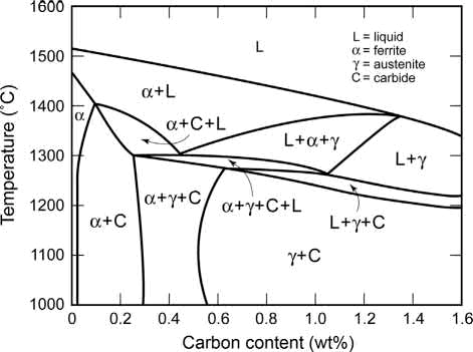
Fig. 22.4 Pseudo-phase diagram for M2 tool steel
Vacuum sintering, which aids in attaining full densification by removing gas from pores, is often used for tool steels. A furnace hot zone with graphite construction can provide the carbon potential needed to avoid decarburization; however, these furnaces are not always equipped for polymer burn-off, requiring a separate thermal-debinding operation. A review of vacuum sintering configuration is found elsewhere. Sintering in N2-rich N2/H2 and N2/H2/CH4 atmospheres have also been demonstrated, although uptake of N2 into the alloy can cause formation of MX carbonitrides in place of MC carbides. This has been reported to increase the sintering window in T15, T42, and M2 tool steels during vacuum sintering, since the carbonitrides act to pin grain boundaries during sintering. This effect is most pronounced in T15 due to the higher V content and thus a greater amount of MC is available to convert to MX carbonitride. The replacement of carbon with N2 in MC carbides frees carbon to the matrix to decrease the solidus temperature, lowering the sintering temperature in steels with high V content, such as T42 and T15. Published sintering data suggest that M2 has the narrowest sintering window of the commonly used tool steels in PIM, and T15 has the widest sintering window. Table 22.3 summarizes published sintering temperatures in various atmospheres for M2, T42, and T15 tool steel. Since A2 and S7 have base carbonyl iron powders with master alloy additions, sintering is very similar to the processing of low-alloy steel.
Table 22.3 Summary of published sintering temperatures in various atmospheres (given in ℃)
Sintering atmosphere | M2 | T15 | T42 |
H2 | 1280 | 1220 | 1200 |
N2/H2 | 1265–1285 | 1225–1275 | 1215–1245 |
1275–1287 1270–1290 | |||
Vacuum | 1210–1220 | 1270 | 1230 |
1253–1257 | 1270–1285 | 1235–1245 |
Several researchers have demonstrated that an increase in carbon of 0.2-0.6 wt.% will decrease the optimal sintering temperature by approximately 25-50℃, as well as increase the sintering window by as much as 30℃, depending on the alloy. This is achieved by a lowering of the solidus temperature with a minimal decrease in the upper-phase boundary limit that leads to excessive microstructural coarsening. It should be noted, however,that a changein carbon content ofthis magnitude can affectthe performance of the steel, and a change in grade may be a better solution.
Heat treating of MIM components can be done using the same conditions as used for conventionally processed tool steels. One concern is carbon content, since the carbon content of the MIM components can vary within the specification, variability in heat treat response can occur. A best practice is to measure carbon content on each lot and adjusts the heat treatment conditions to match. Table 22.4 shows some standard heat treatment conditions for tool steels in both salt and vacuum processes. Multiple temperings are used to reduce the amount of retained austenite and increase the hardness of the tool steel. Microstructures of these high-speed tool steels after salt bath treatment are shown in Fig. 22.5.
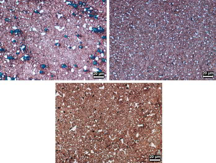
Fig. 22.5 Microstructures of (A) M4. (B) T15. (C) M42 after heat treatment
Table 22.4 Heat treatment conditions used for high-speed tool steels
Alloy | Heat treatment | Austenitize | Quench | Temper |
T15 | Salt bath | 1205°C, 3–5min | 579–593°C, hold 4min | Triple temper 566°C, 2 h |
T15 | Vacuum | 1177°C, 5min | 2 barN2 to below 66°C | Double temper, 538°C, 2 h |
M4 | Salt bath | 1205°C, 3–5min | 579–593°C, hold 4min | Triple temper, 566°C, 2 h |
M4 | Vacuum | 1177°C, 5min | 2 barN2 to below 66°C | Double temper, 538°C, 2 h |
M42 | Salt bath | 1177°C, 3–5min | 579–593°C, hold 4min | Triple temper, 566°C, 2 h |
Table 22.5 Average hardness of various MIM tool steels using heat treatment conditions of Table 22.4
Alloy | Heat treatment | As-sintered hardness, Rockwell C | HT hardness, Rockwell C | Knoop microhardness, converted to HRC |
T15 T15 M4 M4 M42 | Salt bath Vacuum Salt bath Vacuum Salt bath | 52.0 50.5 52.5 52.5 51.0 | 60.5 61.5 62.0 63.5 63.0 | 64.0 64.5 63.0 65.5 65.0 |
The mechanical properties of MIM T15, M4, and M42 high-speed steels that experienced the heat treatment conditions shown in Table 22.4 are provided in this section. These MIM samples were sintered for 30min at 1285℃ for the T15, 1260℃ for the M4, and 1220℃ for the M42. Table 22.5 shows the average of ten hardness measurements of the different tool steels. Notice the difference between heat treatment method and Rockwell hardness and Knoop hardness.
These same tool steels were evaluated for wear behavior using a modified ASTM G65-94 test. In this case, the specimen dimensions were 6.3mm diameter ×37mm long and the testing conditions were 6000 revolutions at 200 r/min with a force at sample of 13 N. Wear results are shown in Fig. 22.6. Wear resistance is slightly greater for steels heat treated in a salt bath than for steels treated in a vacuum. T15 and M4 exhibit better wear resistance than M42.
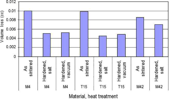
Fig. 22.6 Comparative ASTM G65-94 wear results of various MIM tool steels that were heat treated using the conditions given in Table 22.4. The T15 shows the least wear in the heat treated condition.
Contact: Cindy Wang
Phone: +86 19916725892
Tel: 0512-55128901
Email: sales1@atmsh.com
Add: No.6 Huxiang Road, Kunshan development Zone, Jiangsu
Shanghai Branch: No. 398 Guiyang Rd, Yangpu District, Shanghai, China