Metal injection molding (MIM) can provide unique thermal management solutions to dissipate heat from microelectronic devices. Heat sinks with increasing shape complexity are being designed for more efficient heat transfer. MIM allows the necessary design freedom and provides a cost-effective means of fabricating the high quantities of heat sinks needed for microelectronics. This chapter reviews the processing conditions for MIM processing of specific materials used for thermal management and provides examples of MIM heat sink components.
The increasing power requirements and decreasing size of high-performance microprocessors present heat dissipation challenges in microelectronic package designs. High-thermal conductivity materials are required, and in some cases, they must also have a low-thermal expansion coefficient. Advanced heat sink designs handle increasing thermal loads by using aerodynamic fins, heat pipes, and microchannels. Components with these structures can be readily produced in large quantities by MIM from well-known thermal management materials, including Cu, W-Cu, and Mo-Cu.
The most widely used method for extracting heat from a microprocessor is to connect it to a heat sink, which might be air-cooled, either actively or passively. The active designs require fans or pumps to circulate fluids for heat extraction, often leading to heat generation, power drain, and new failure modes. Passive designs have fins for increased surface area to increase the amount of heat that they can release to the ambient air. Both cases require high-thermal conductivity materials to transfer heat from the device to the fluid stream.
Many early heat sinks were extruded from Al alloys. Extrusion is a highly automated, low-cost, high-volume process, but it inherently limits the fin geometry. Further, the alloying elements added to improve extrudability lower the thermal conductivity. Machining of extruded Al alloys or die-casting can produce fins with a higher height to gap ratio, but at a higher cost. Likewise, folded-fin heat sinks can give a twofold improvement over the performance of extruded heat sinks, but also with an increased cost.
MIM enables greater flexibility in design over extrusion and die casting. For example, round pin fins are easy to produce by MIM, but machining from an extruded Al alloy is limited to square fins. The performance difference between a heat sink with round pins fabricated by MIM and one machined with square pins is shown in Fig. 20.1. Other fin geometries are also possible with MIM, such as tapered pin fins and aerofoil-shaped fins, as shown in Fig. 20.2. Heat sinks are often larger than typical MIM parts. Heat sinks up to 50mm high by 50mm wide by 50mm long are most amenable to MIM processing.

Fig. 20.1 Comparison of the thermal performance of a machined heat sink with square pins and a MIM heat sink with round pins
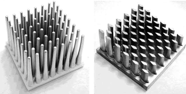
Fig. 20.2 Examples of heat sink geometries possible with MIM
Further increases in heat dissipation capability are possible by integrating a heat pipe into the heat sink. These phase-change cooling devices work by vaporizing a fluid in a hot zone, which absorbs heat. The vaporized fluid travels to a cold zone where it condenses to release heat and the liquid is wicked back to the hot zone. The effective thermal conductivities of these heat transfer devices can be much higher than that of Al or Cu. Powder metallurgy techniques, including MIM, can fabricate a porous wicking structure into a heat sink to produce an integrated heat pipe. Heat pipes can be miniaturized by producing them from wickless, noncircular microchannels, which can also be fabricated by MIM.
Heat sinks are designed to remove heat from electronic packages, but packages must be designed to extract the heat directly from the semiconductor device or a heat spreader can be used to transfer heat from the back of the device to the heat sink. In both cases, high-thermal conductivity is desirable, but a thermal expansion coefficient of 4-7 ppm/K is also required for compatibility with silicon to minimize thermal fatigue from off-and-on device operation.
In addition to thermal management, electronic packages also provide structural support for the semiconductor device, protection from the environment, and interconnections for power and signals. To meet these requirements, electronic packages are usually thin-walled enclosures with holes for interconnections that can be hermetically sealed with glass. The Fe-Ni-Co alloy F-15, also known by its trademark name, Kovar , is commonly used for electronic packages due to its low-thermal expansion coefficient and good glassto-metal sealing capability, but it suffers from a low-thermal conductivity.
Sintered packages, such as those shown in Fig. 20.3, must have a closed pore structure to provide hermetic sealing, thus sintered densities must be over about 92% of theoretical. Dimensions typically range from 8mm to 125mm with wall thicknesses of 1-3mm. Tolerances are very exact with typical values of ±25 μm on a linear dimension. Heat spreaders have similar sizes and tolerances, but lack holes. Heat spreaders or packages that are directly bonded to a semiconductor device have typical flatness requirements of ±0.025mm per 25.4mm. Some surfaces can be finish ground, but others are not easily corrected for flatness. Packages are often assembled by brazing, which requires the MIM surface to be plated. The surface porosity of MIM parts can cause plating difficulties, which can be overcome by special techniques.
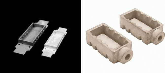
Fig. 20.3 Examples of electronic package geometries possible with MIM
Copper is often used for applications that require higher-thermal conductivities than possible with Al. Its lower-thermal expansion coefficient also helps reduce thermal fatigue problems. Copper is more difficult to extrude, stamp, machine, or cast than Al, but it is better suited to processing with powder metallurgy techniques, including MIM.
Although the thermal expansion coefficient of Cu is lower than that of Al, it is still considerably higher than those of the silicon chip or ceramic substrate, providing challenges to mounting the heat sink. Accordingly, composite materials, such as W-Cu and Mo-Cu, which combine high-thermal conductivity with a low-thermal expansion coefficient, are more suitable for packaging applications. The components of these composites have widely differing melting temperatures and do not alloy, so they are usually processed using powder metallurgy techniques. Traditional methods of processing W-Cu and Mo-Cu include sheet-rolling operations and Cu infiltration of pressed and sintered W or Mo compacts. These techniques are generally used to fabricate electrical contact materials, which have relatively high-volume fractions of Cu and low degrees of shape complexity. MIM can be used to produce porous W and Mo skeletons or mixed W-Cu and Mo-Cu powders can be injection molded and sintered to meet heat sink design requirements.
Tungsten with 10-20 wt% Cu is a common heat sink composition. Molybdenum with similar Cu contents has a lower-thermal conductivity, but its lower density makes it attractive for applications where weight is important. Typical properties of MIM Cu, W-15Cu, and Mo-18Cu are given in Table 20.1. These Cu contents for W-Cu and Mo-Cu maximize the thermal conductivity for a thermal expansion coefficient that is acceptable for most packaging applications. As discussed in later sections, theoretical thermal conductivities are not usually obtained.
Table 20.1 Typical properties of heat sink materials
Property | Cu | W-15Cu | Mo-18Cu |
Density (g/cm3) Thermal conductivity (W/(mK)) Thermal expansion coefficient (ppm/K) | 8.5 320-340 17.0 | 15.6–16.2 180–190 7.2 | 9.3–9.5 140–160 7.0 |
Measurement of thermal performance is not trivial. Thermal conductivity λ is most commonly determined from the thermal diffusivity α as measured by the laser flash method (ASTM E1461) according to the relationship.

where Cp is the specific heat and ρ is the sample density. This method requires diskshaped samples and requires great care to minimize measurement variability.
Electrical conductivity is much easier to measure and does not depend on the geometry of the sample. For Cu and other elemental metals, the electrical conductivity σ can be measured by the four-point probe method and converted to thermal conductivity λ using the Wiedemann-Franz relationship.

where L is the Lorenz number (2.28×10⁻⁸V2 /K2 for Cu at 25℃) and T is the absolute temperature in Kelvin. Factors, such as porosity and impurities, that lower the electrical conductivity also proportionally lower the thermal conductivity. This method is not suitable for composites, such as W-Cu or Mo-Cu, whose components have different Lorenz numbers, or electrical insulators, which conduct heat via phonons.
While the thermal conductivity is an important factor, the overall thermal performance of heat sinks is better characterized by the thermal resistance. Thermal resistance in K/W is a measure of the temperature difference across the boundary between the heat sink and the ambient air as a certain amount of heat energy is passed through it. It considers the overall design as well as the material thermal conductivity and is affected by external factors such as air temperature and air flow. More efficient heat sinks have lower-thermal resistances. The thermal resistance is often calculated in the design phase and measured for verification during testing of prototypes.
MIM of unalloyed Cu powders for applications associated with heat dissipation in electronic systems has been frequently demonstrated. Many types of Cu powders are commercially available and have proven adequate for molding with conventional binder systems. The primary challenge is attaining high sintered densities and high conductivities, which requires sintering to nearly full density while reducing oxygen and other impurities to a low level. Copper is especially susceptible to hydrogen-induced swelling during sintering. Oxides in closed pores can react with hydrogen to generate trapped water vapor, which increases the gas pressure in the pores, leading to pore swelling, inhibited densification, and component blistering. Accordingly, MIM of Cu requires attention to oxygen control in the initial powder and via reduction during sintering. The key requirements for processing high-thermal conductivity Cu components via MIM are described in the following section.
Table 20.2 Cu powder characteristics
Production method | Oxidereduced | Wateratomized | Gasatomized | Jetmilled |
Oxygen content (wt.%) | 0.332 | 0.223 | 0.379 | 0.214 |
Particle size distribution | ||||
D10 (μm) | 5.9 | 7.8 | 4.1 | 4.7 |
D50 (μm) | 11 | 13 | 8.2 | 7.9 |
D90 (μm) | 17 | 23 | 13 | 12 |
Pycnometer densitya (g/cm3) | 8.62 | 8.48 | 8.84 | 8.75 |
Apparent density (g/cm3) | 2.8 | 3.6 | 3.9 | 3.4 |
% of pycnometer | 32% | 42% | 44% | 39% |
Tap density (g/cm3) | 3.6 | 4.4 | 4.2 | 4.3 |
% of pycnometer | 42% | 52% | 47% | 48% |
aTheoretical density is 8.96 g/cm3
Copper powders are produced by many processes including chemical precipitation, electrolytic deposition, oxide reduction, water atomization, gas atomization, and jet milling. Accordingly, Cu powders are commercially available in a wide range of particle shapes and sizes. Electrolytic and chemical powders exhibit poor packing and poor rheology in molding, so they have been largely unsuccessful for MIM. Characteristics of examples of the other types are summarized in Table 20.2. Representative scanning electron micrographs are given in Fig. 20.4. These powders all have similar particle sizes but different morphologies. Typical purities reported by the manufacturers are about 99.85 wt%; however, oxygen contents can range up to 0.76 wt%. Powders are usually shipped containing desiccant and proper powder storage is essential to avoid oxidation between purchase and use.
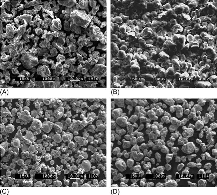
Fig. 20.4 Scanning electron micrographs of (A) 11μm oxide-reduced Cu powder. (B) 13μm water-atomized Cu powder. (C) 8μm gas-atomized Cu powder. (D) 8μm jet-milled Cu powder
All the Cu powders in Table 20.2 are suitable for MIM without further treatment, but each has a different advantage. The jet-milled Cu powder has the lowest impurity level. The gas-atomized powder has the highest tap density, which generally translates into higher solids loadings to promote ease of MIM processing. The oxide-reduced and water-atomized powders are lower cost, which is a critical concern when competing against wrought and cast Cu. Finer powders than those in Table 20.2 are more expensive, more difficult to mold, and provide little sintering advantage. Costs do not substantially decrease with coarser powders but give concerns with dimensional control and sintering behavior.
Wax-polymer binders are generally compatible with Cu powders. Copper feedstock compounded with a wax-polymer binder is commercially available, but Cu feedstock is not available with the BASF Catamold binder since the nitric acid used in debinding dissolves Cu. As an alternative, an agar-based binder system can be used. The optimal solids loadings in a MIM Cu feedstock depends on the powder morphology and packing characteristics, so it can vary widely depending on the powder selection. Typical solids loadings with a polymer-wax binder are 48-52 vol% for oxidereduced powders, 52-56 vol% for water-atomized and jet-milled powders, and 65-70 vol % for gas-atomized powders. These solids loadings translate into average tooling scale-up factors of 1.24 for oxide-reduced powders, 1.21 for water-atomized and jet-milled powders, and 1.12 for gas-atomized powders, assuming a final sintered density of 95% of theoretical.
Table 20.3 Examples of MIM Cu feedstock preparation
Binder | Powder type | Particle size (μm) | Solids loading (vol%) | Mixing technique |
45% acrylate copolymer 23% polypropylene 23% wax 9% dibutyl phthalate | Not given | 11 | 56 | Not given |
Paraffin-based with 2 other components | Gas atomized | 15–45 | 70 | Twinscrew |
12% agar 12% glucose 76% deionized water + biocides | Not given | 22 | 70 | Sigma |
55% paraffin wax 40% polypropylene 5% stearic acid | Water atomized | 13 | 52 | Twinscrew |
50% polypropylene 35% paraffin wax 10% polybutyl methacrylate 5% stearic acid | Oxidereduced | 7, 10, and 14 | 48 | Z-blade |
65% paraffin 30% polyethylene 5% stearic acid | Gas atomized | 10 | 66 | Banbury |
Polyethylene, paraffin wax, stearic acid, and potassium carbonate | Gas atomized | 22 | 63 | Z-blade |
Examples of several different Cu feedstocks are summarized in Table 20.3. Moldable feedstock has been produced with various types of mixers as well as an assortment of Cu powders. A key issue with mixing is the avoidance of contamination from previously mixed materials and wear of the mixing vessel to maintain high-thermal conductivities in the final parts.
Molding Cu feedstocks is relatively straightforward, although their relatively highthermal conductivities result in faster cooling rates, making it more difficult to fill thin-walled components. As with mixing, cross-contamination must be avoided during molding to maintain high-thermal conductivities. For MIM Cu, high injection speed or pressure can cause the binder to separate from the Cu powder, which can be deformed into a rigid solid due to its low-yield strength. Copper powders with oxidized surfaces have better adhesion to the binder than hydrogen-reduced Cu powders.
Gas-atomized powders have been used for molding large, complex heat sinks. These parts have masses of 100-150 g and hollow structures with wall thicknesses as small as 0.3mm. Molding such parts generally requires multiple slides, a hot-runner, and a cavity pressure transducer, but the biggest challenge is mold temperature control prior to part ejection. A combination of electrical heaters and water temperature control units has proven successful at molding tubes about 25mm long with 0.3mm wall thickness. A high injection temperature and warm die required a cooling time of 5min, but this was still much faster than heating and cooling the die, which required a cooling time of 15min. Three-dimensional simulations that include analysis of the heating and cooling of the mold can accurately predict filling behavior.
Copper parts can be conventionally debound using solvent and/or thermal techniques. Thermal processes require careful atmosphere control to minimize residual carbon and oxygen, which can negatively affect densification. Thermal debinding as-molded parts containing a wax-based binder in air can cause cracking due to endothermic reactions, while debinding in argon can lead to slumping. Vacuum debinding provides good dimensional control and intermediate levels of carbon and oxygen. Solvent debinding followed by thermal debinding in hydrogen has also proven successful.
Oxygen must be reduced early in the sintering cycle to avoid entrapment of water vapor in closed pores, which is often accompanied with rapid grain growth and pore separation from grain boundaries, leading to high porosities. The addition of reactive dopants, such as Al, Cr, and Si, can help getter oxygen, but degrade conductivity. Extraction of oxygen prior to final stage pore closure, which occurs near 92% density, generally requires hydrogen sintering with carefully designed thermal cycles.
During heating, the reduction of copper oxides by dry hydrogen typically occurs in the range from 550℃ to 680℃. Long hold times at temperatures in this range, or higher, can eliminate swelling by reducing the copper oxides prior to final stage sintering pore closure. Maximum temperatures near the melting temperature of Cu (1080℃) are required for high sintered densities. For example, high densities have been achieved by debinding and sintering in dry hydrogen using the following thermal profile:
3℃/min to 300℃, hold for 1 h.
3℃/min to 500℃, hold for 1 h.
3℃/min to 600℃, hold for 1 h.
5℃/min to 700℃, hold for 2 h.
5℃/min to 800℃, hold for 2 h.
5℃/min to 900℃, hold for 2 h.
5℃/min to 1050℃, hold for 1 h.
The onset of pore closure depends on the powder. The densities of the four different powders given in Table 20.2, uniaxially pressed at 175MPa, after different stages of the previously mentioned cycle are plotted in Fig. 20.5. At 700℃, the density is about the same as the initial green density. Most of the sintering densification occurs during heating at temperatures between 700℃ and 900℃. From 800℃ to 900℃, the density of the gas-atomized powder increases from 80% to greater than 90%. Thus, the oxides in this powder must be reduced below 900℃ to prevent water vapor entrapment. The remaining powders have open porosity that allows further reduction during heating to 1050℃. The densities after sintering at 1050℃ range from 93% to 96% regardless of production method. Copper powders with mean particle sizes up to 25μm can also achieve this level of densification at 1050℃. Finer powders have higher starting oxygen contents and will densify at lower temperatures, leading to a higher probability of trapping water vapor in closed pores.
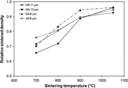
Fig. 20.5 Effect of sintering temperature on the density of four types of Cu powders uniaxially pressed at 175MPa
Fig. 20.6 confirms that the thermal cycle enables nearly complete oxide reduction of the gas-atomized powder by 900℃. The oxygen content is also 200 ppm or less for the other powders, except for the oxide-reduced powder, which contained 400 ppm oxygen. The density of the oxide-reduced powder at 900℃ is 89% of theoretical, so some open porosity remains to allow for continued reduction and the escape of water vapor.
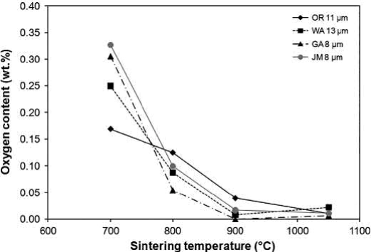
Fig. 20.6 Effect of sintering temperature on oxygen content for four types of Cu powders uniaxially pressed at 175MPa
Microstructures of the water-atomized powder after sintering at 900℃ for 2 h and at 1050℃ for 1 h are shown in Fig. 20.7. At 900℃, the grains are small and small pores are visible at the grain boundaries. At 1050℃, both the grains and the pores have significantly coarsened with a slight increase in overall density. The large pores indicate that even with oxygen levels below 200 ppm at 900℃, sufficient oxygen remains to produce entrapped water vapor in the small pores and cause them to swell when heated to 1050℃. On the other hand, the microstructure of the oxide-reduced powder sintered at 1050℃ for 1 h, shown in Fig. 20.8, consists of relatively small pores, indicating little swelling from entrapped water vapor.
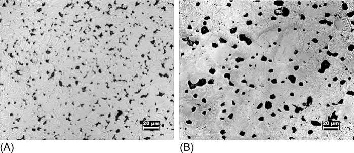
Fig. 20.7 Micrographs of a 13μm water-atomized powder after pressing at 175MPa and sintering in hydrogen at (A) 900℃ for 2 h. (B) 1050℃ for 1 h
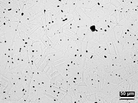
Fig. 20.8 Micrograph of a 11μm oxide-reduced Cu powder after pressing at 175MPa and sintering in hydrogen for 1 h at 1050℃
Thermal conductivities of MIM Cu range from 280 to 385W/(m K), depending on porosity and impurities. Porosity of 4%-7% is typical, while Fe contents can range from 20 ppm to 570 ppm. In comparison, the thermal conductivities of commercially pure wrought Cu alloys, such as C11000, can reach 390W/(mK) for metallic impurity levels below 50 ppm and oxygen contents as high as 0.04 wt%. Commercially pure cast Cu alloys, such as C83400, have lower thermal conductivities, usually around 340-350W/(m K), because of the use of deoxidizers such as Si, Sn, Zn, Al, and P. These elements likely comprise the majority of the 0.15 wt% of impurities typically found in commercially available Cu powders.
Based on the Wiedemann-Franz relationship and Nordheim's Rule, the predicted effect of Fe impurities on the thermal conductivity of Cu is plotted in Fig. 20.9 for comparison with experimental results. The measured values follow the same trend as the model predictions, but for most of the samples, the measured thermal conductivities are lower than expected based on just Fe impurities. At low concentrations, Fe may be representative of the overall impurity content, and the thermal conductivity is reduced by the cumulative effects of all impurities. The highest Fe concentration likely results from contamination during processing.
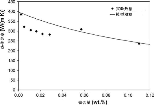
Fig. 20.9 Effect of iron impurities on the room temperature thermal conductivity of Cu in comparison to experimental results
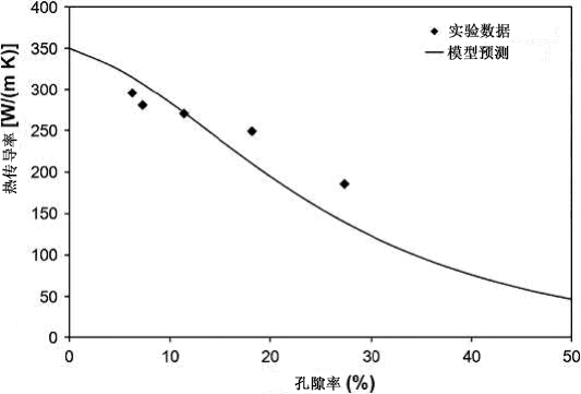
Fig. 20.10 Effect of porosity on the room temperature thermal conductivity of Cu in comparison to experimental results
In addition to impurity effects, porosity also decreases the thermal conductivity of MIM Cu heat sinks as shown in Fig. 20.10. Experimental data show slightly less dependence on porosity than predicted by the relationship assuming a value of 350W/(m K) for the porefree thermal conductivity (to consider impurity effects). Impurity concentrations on the order of 0.1-0.2 wt% can be as detrimental to the thermal conductivity as 20% porosity.
MIM Cu must compete with well-established machining and casting processes. MIM can provide a more cost-effective means of producing complex shapes than machining wrought Cu. Commercially pure Cu alloys are difficult to cast and the thermal conductivity of MIM Cu is much higher than easily castable alloys, such as C83400, owing to their high levels of alloying additions. Still, successful MIM of Cu depends on achieving the right balance of powder cost, moldability, dimensional control, sintered density, and thermal conductivity.
MIM can produce the heat sink geometries shown in Fig. 20.2 in high-conductivity Cu. As another example, a MIM Cu heat sink measuring approximately 20mm wide by 20mm long by 2.5mm high is shown in Fig. 20.11. This part was produced from a water-atomized powder, which was mixed at a solids loading of 52 vol% with a waxpolymer binder. After molding, the components were solvent debound to remove the wax. The remainder of the binder was burned out during heating in the sintering cycle. The sintered density was 94% with a thermal conductivity of 296W/(mK).
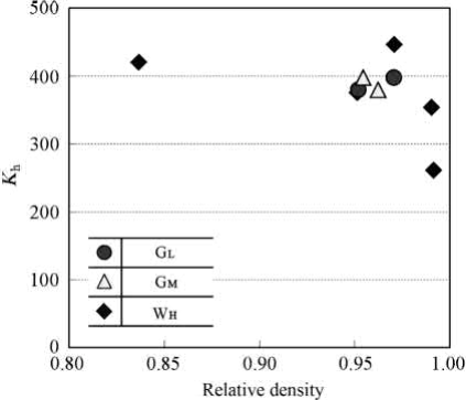
Fig. 20.11 An example MIM Cu heat sink. This demonstration component is approximately 20mm wide by 20 mm long by 2.5mm high
MIM Cu has also been used to produce heat sinks in which the pins are replaced with thin-walled tubes for increased surface area. Parts have been demonstrated consisting of 96 tubes with lengths of 29.2mm, outer diameters of 3.65mm, and inner diameters of 3.05 mm. Sintered densities of 94% of the- oretical were achieved without significant distortion of the tubes. Sintered Cu structures with large length to thickness ratios must be handled carefully to avoid deformation due to the low-yield strength of fully annealed Cu.
As another example, two-material MIM has been used to fabricate Cu heat pipe structures. In this process, a coarse Cu powder is molded to form the wick and a fine Cu powder is co-molded around it. This composite structure is then thermally processed in such a way that the two sections co-sinter together to produce a good metallurgical bond. A demonstration heat pipe is shown in Fig. 20.12 along with a cross-section showing the interface between the outer wall and the wick. This design integrates cooling fins with the outer casing, which surrounds the porous wick and a large open vapor channel. MIM enables seamless transitions between these features to eliminate thermal interface resistance.
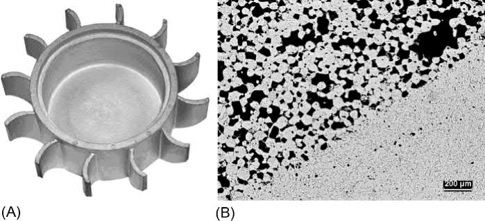
Fig. 20.12 (A) A demonstration heat pipe. (B) A micrograph of the interface between the outer wall and the wick
Contact: Cindy Wang
Phone: +86 19916725892
Tel: 0512-55128901
Email: [email protected]
Add: No.6 Huxiang Road, Kunshan development Zone, JiangsuShanghai Branch: No. 398 Guiyang Rd, Yangpu District, Shanghai, China