In order to take full advantage of the metal injection molding process, we need to consider many key aspects of MIM design. A clear understanding of these principles will ensure the best manufacturing results for MIM parts. In addition, we will help you analyze the benefits and costs of the MIM design phase.
The MIM Design Guide is a reference for applying new part design principles and evaluating manufacturing possibilities for existing parts. Proper MIM design will maximize economic efficiency and ensure that MIM parts have the target geometry and dimensions.
During the MIM design process, you need to consider manufacturing design principles to eliminate any costly secondary operations.
During the sintering process, the volume of the green part shrinks by about 20%. To minimize the possibility of distortion, we need to fully support the green part.
It is ideal to design MIM parts with large planes, or several parts with common planes, so that we can use standard fixtures. Otherwise, we need specific fixtures or retainers for parts with long spans, cantilevers, or vulnerable points.
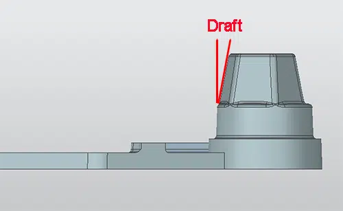
This is a small angle on the part surface, parallel to the direction of mold movement. The draft slope is used to facilitate mold release and demold. Its normal range is from 0.5° to 2.0°. Once the surface of a single component element is texted, a larger draft slope should be used.
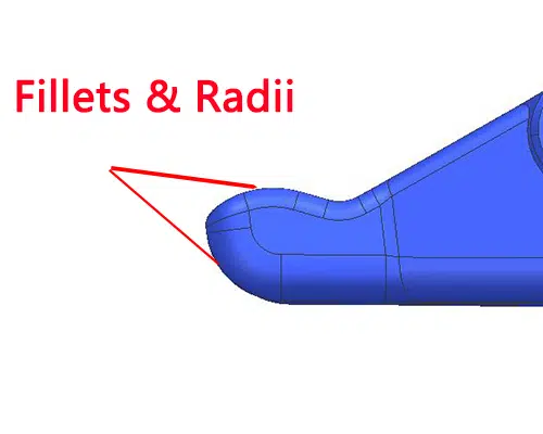
We usually apply rounded corners and radii to reduce the characteristic intersecting stresses of the production function. They play an important role in the molding process by eliminating sharp corners, material flow and jet marks. This is an effective way to deal with sharp corners. Rounded corners and radii of 0.4 to 0.8 mm are usually preferred.
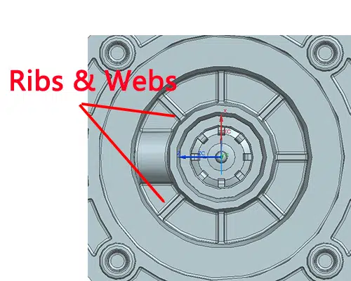
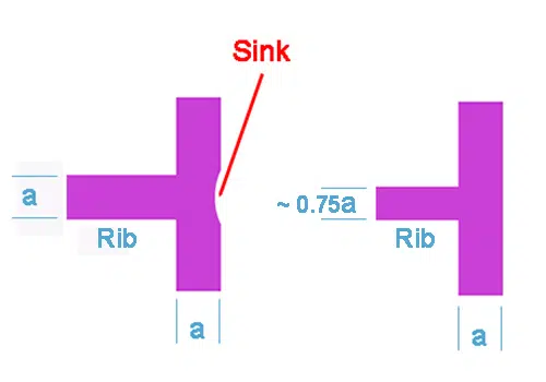
Ribs and webs are conventional features for strengthening relatively thin walls and avoiding thick sections. In addition, they improve material flow, limit deformation and increase the strength and stiffness of thin walls. The thickness of the ribs should be less than that of the adjacent wall, otherwise we should use multiple ribs according to the structural requirements.
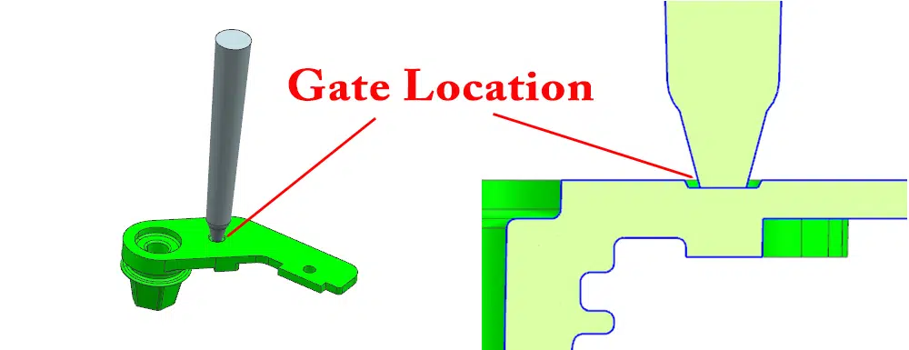
Since injection gates always mark the finished part, their location should balance the requirements of manufacturability, function, dimensional control and aesthetics. Its optimal location is on the parting line of the mold, a location that will allow the runner to impact the cavity wall or core pin. We need to consider other factors for gate locations such as subgates, precision gates and tunnel gates. For MIM parts with varying wall thicknesses, we will place the gate at the thickest cross section to allow the MIM material to flow from the thick section to the thin section. This approach will reduce voids, depression marks, concentrated stresses and flow lines on the part surface. In a multi-cavity MIM process, we must consider gate size and placement to ensure that MIM material is delivered to each cavity at a balanced fill rate.
Minimize settlement and weave lines during the design process. Subsidence always occurs in the same thickness of the wall and in the thick portion of the rib. Reducing the rib thickness to 75% of the wall will eliminate potential depressions.
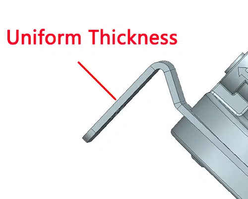
The overall size and design of the MIM part will determine the cross-sectional wall thickness. Typically, the optimum wall thickness is 1 mm to 6 mm, which is variable for different overall dimensions. We should uniform wall thickness under feasible conditions to avoid uneven shrinkage, deformation, internal stresses, voids, cracks, dent marks, dimensional and tolerance disturbances due to thickness variations. The thickness should preferably be 1-6 mm. we can still remove the material in both directions to create wall thickness uniformity and thus save the cost of fine metal powders in an economical way.
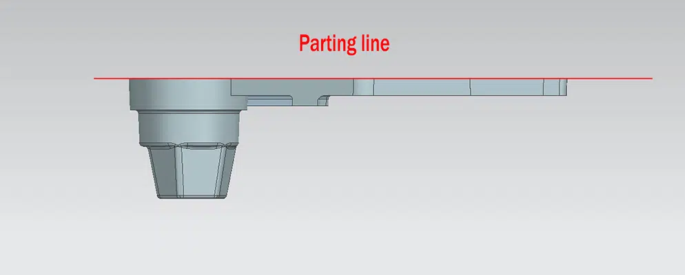
The parting line is the plane where the two halves of the mold intersect and all features need to be perpendicular to the parting line in order to be removed from the mold. Often, parting lines are transferred to the part surface as witness lines, and we can design parting lines so that they separate along inconspicuous edges to hide it. It is best to include the parting line in a plane.
We also noted the following part improvement designs.
Coring holes are typically used to reduce the cross section of MIM parts, uniform wall thickness, reduce metal material consumption, and reduce or eliminate secondary machining operations. The preferred orientation is parallel to the mold opening and perpendicular to the parting plane. When the length/diameter ratio is greater than 4:1, through holes are preferred because the ends support core pins; otherwise, blind holes are used with cantilever pins.
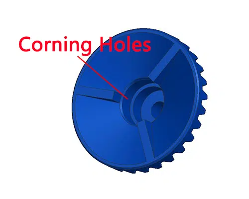
Holes and slots can provide functional features in MIM parts at no additional cost, in addition to reducing part mass and uniform wall thickness. Holes are perpendicular to the parting line and easy to form at minimal cost, these holes are parallel and require mechanical rams or hydraulic cylinders. For internal connection holes, we need to carefully consider potential sealing problems and flooding issues.
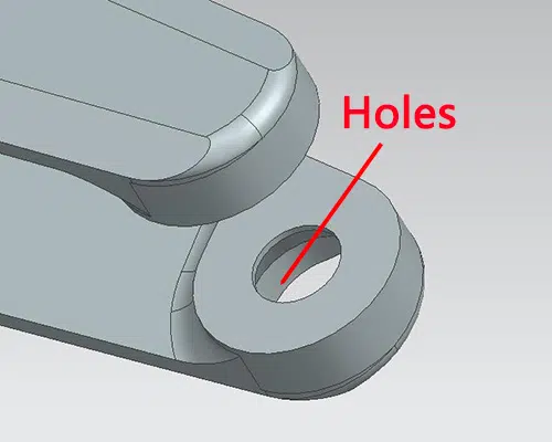
The outer cutout is easily formed on the parting line by the parting die. While the inner cutout can only be created by the slider or collapsible core. In MIM design, we should avoid internal cutout because it will increase the cost and may have flashing edge problem.

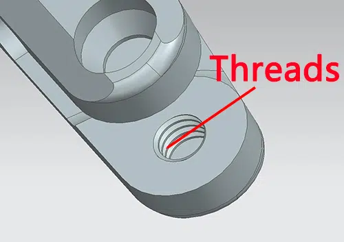
Both internal and external threads can be formed in the MIM process. Internal threads are more accurate and less costly than screwed cores. The best location for male threads is on the parting line. To maintain tolerances on the thread diameter, the narrow flat is typically 0.005".
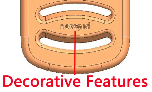
MIM makes it easy to mold features such as logos, knurling, part numbers and identification markings into place without added cost, all of which can be raised or under-surfaced. We can also take pride in the high level of feature detail such as diamond knurling in the MIM process.
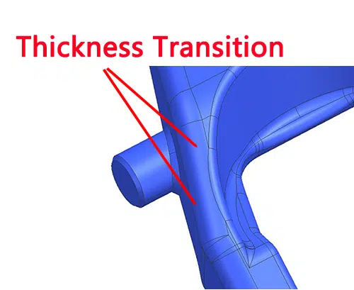
Although the wall thickness of MIM parts is ideally uniform, a uniform core thickness is not a perfect choice and it is difficult to avoid variations. We need to design gradients between different thicknesses.
Contact: Cindy Wang
Phone: +86 19916725892
Tel: 0512-55128901
Email: [email protected]
Add: No.6 Huxiang Road, Kunshan development Zone, JiangsuShanghai Branch: No. 398 Guiyang Rd, Yangpu District, Shanghai, China