Powder injection molding comprises several processing steps, and defects may occur in each step if care is not taken. The defects encountered could be caused by mechanical factors, such as poor mold design and mold manufacturing, or by processing related factors, such as incomplete kneading, inadequate molding pressure, injection speed, holding pressure, and nonoptimized debinding and sintering parameters . Some of these defects may originate in the early processing steps but are difficult to identify because they do not manifest until after debinding or sintering. In the following section, the defects that frequently occur in each processing step are examined and their causes are explained. Hopefully, with an understanding of the scientific background of the defects, exhaustive trial and error experimentation can be avoided.
The raw powders used for metal injection molding (MIM) are usually quite fine, mostly below 20μm, and thus agglomeration could be serious. When hard agglomerates, which cannot be broken up during high-shear-rate kneading, are included in the feedstock, the final sintered product could then contain inhomogeneous microstructures. If the agglomerates are alloying element additions, highly alloyed areas will develop and cause lean-alloyed regions, which will affect the mechanical properties. Moreover, the highly alloyed region may also have low density after sintering, as shown in Fig. 12.1, since the agglomerated alloying elements, such as Mo, may not be densified at the sintering temperature. Owing to unbalanced interdiffusion, other alloying elements, such as nickel, when too large or agglomerated, may also develop Kirkendall pores that are too large to be annihilated.
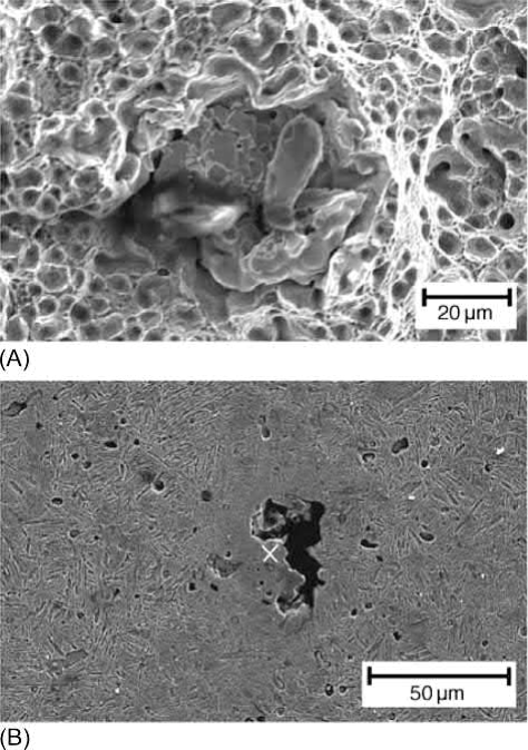
Fig. 12.1 (A) Fracture surface showing Mo agglomerates. (B) Large voids in Mo-rich region.
The uniformity of the feedstock constituents is always a concern in kneading.If the kneading time and shear rate are insufficient, the metal powders will not be uniformly distributed. Some pockets of organic binders may also exist and cause blistering during the subsequent thermal debinding process. In addition, with excessively long kneading time, decomposition or evaporation of low-temperature binder components will occur. The optimized kneading time can be determined by monitoring the power input to the kneader. When the power decreases and becomes steady, the feedstock is ready and should contain uniformly distributed powders and binders. This uniform distribution and lot-to-lot consistency can be confirmed using a pycnometer density meter or a capillary rheometer.
To lower the manufacturing cost of MIM products, the gate, runner, sprue, and green parts with defects are usually recycled. Two methods are usually adopted by the MIM industries. The first methodisto add 30%-50% recycled feedstocks to fresh materials, while the other is to use 100% recycled materials. Unfortunately, these feedstocks deteriorate as the number of recycling iterations increases. The main cause of the deterioration of feedstock is oxidation of the binder components, particularly in the case of paraffin wax, caused by the transformation of the C―C chain to the C]O chain. The backbone binder, such as polyethylene, also deteriorates during recycling. These deteriorations cause decrease of the intrinsic binder strength and weakening of the bonding at the powderbinder interface and thus lower green strength. The loss of the lubrication effect of the binder among powders also results in higher viscosity. This means that the lot-to-lot dimensions and green densities will be difficult to control. Consequently, the molding parameters, including injection pressure and barrel temperature, should be readjusted with recycled feedstocks. In addition, as a result of the weaker bonding between powders and binders, more cracks and distortions of production parts may result during solvent debinding with further iterations of recycling, as shown in Fig. 12.2 for feedstocks recycled six and eight times.
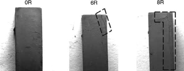
Fig. 12.2 The surface condition of the specimen after solvent debinding in 50℃ heptane for 4 h. More defects can be found in the specimens prepared with highly recycled feedstocks (6R and 8R).
When high numbers of cavities are built in the mold, long runners are required. This requires a high molding pressure to transport materials to each cavity. When a high molding pressure is applied, flash usually occurs, as shown in Fig. 12.3, unless the molds are perfectly clamped without any clearance. Since the materials and shapes of the mold components are different, different amounts of elastic deformation and, in some cases, even plastic deformation, will occur and create clearance between tooling components. As a result, materials will be forced into the clearances. This problem becomes even more serious when large molds with large numbers of cavities and undersized molding machines are used, because the stiffness of the mold and the precision of the mold dimensions become more difficult to control.
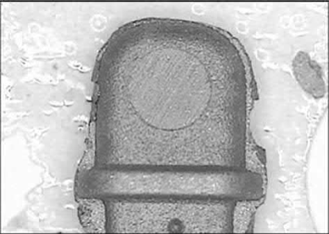
Fig. 12.3 Flashes occur when the feedstock is forced into the clearances between mold components under high molding pressures.
Another defect, which is caused during molding but does not appear until the later processing steps of solvent debinding or thermal debinding, is residual stress. This stress is frozen in owing to the rapid cooling by the relatively cold mold surfaces. When this stress is relieved during heating in the debinding stage, either in solvent debinding or in the early stage of thermal debinding, distortion could occur. If a high injection pressure is applied, distortion may even occur for parts sitting at room temperature for a long time.
Another common defect of cosmetic parts is a poor appearance around the gate. As the feedstock passes through the narrow gateintothe die cavity, binder separation can occur due to powder migration from a high-shear-rate region to a low-shear-rate region. This binder/powder separation becomes more serious at the end of the filling stage and during the pressure holding stage, wherein the feedstock flows slowly and the pressure builds up rapidly. To fill in the clearance in the die cavity resulting from thermal shrinkage, more feedstock is pushed into these openings by the holding pressure. Since the movement of the metal powders in the feedstock is slow, due to the high interparticle friction, the binder, which has a low viscosity, is forced to flow through interparticle interstices. Thus, the binder content at the gate areas is increased, causing molding defects, particularly at the gate, where the shear rate is the highest. If the bonding between the powder and the binder is weak, separation will occur easily and form binder-rich areas at the surface of the part near the gate, as shown in Fig. 12.4. This gate mark remains after sintering, since the solid content in this region is low and thus the appearance is different. Postsintering surface treatment, such as sand blasting or coating, is often applied to eliminate or alleviate this problem. Development of new binders that can reduce the gate mark is still a focus of research. Occasionally, the binder-rich area at the surface of the part may delaminate from the bulk or form a hidden delaminated void near the surface. When a postsintering secondary operation, such as drilling, is applied, these defects will then be noticed, as shown in Fig. 12.5. In some cases, gate redesign helps to alleviate this powder/binder separation problem. If the original gate has a narrow opening and is located at a thin section, it can be enlarged and relocated to a thick section. As a result, the level of binder/powder separation will be reduced and the flow marks and weld lines will be minimized.
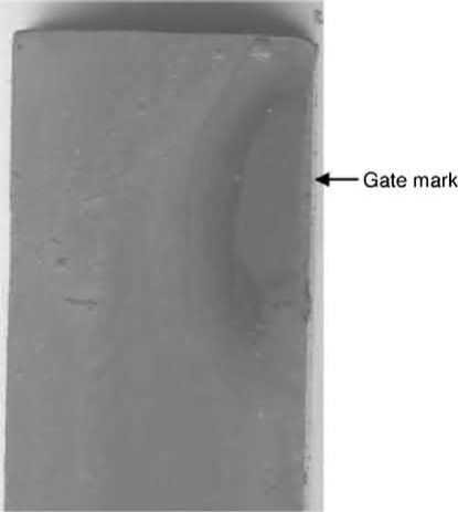
Fig. 12.4 With a high shear rate at the gate, powder/binder separation occurs and binder-rich gate marks form.

Fig. 12.5 Powder/binder separation occurs and delamination is observed after drilling.
Other defects in MIM parts are similar to those found in conventional plastic injection molding due to improper molding parameters. When the molding pressure or holding pressure is low, low green density areas and incomplete filling can occur, as shown in Fig. 12.6. When combined with poor venting design and early solidification at long runners or sprue, internal voids may also develop in thick sections. After sintering, these regions with low density or internal voids could form concave sink marks.
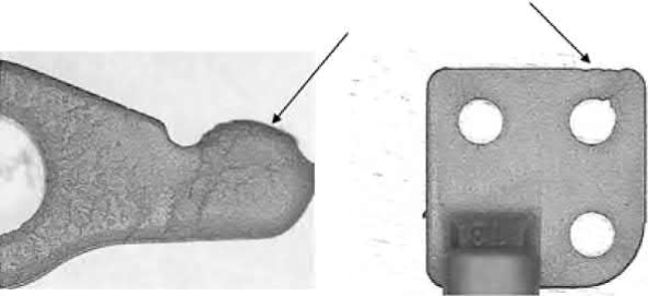
Fig. 12.6 Incomplete filling occurs when the molding pressure is too low.
Weld lines and flow marks are caused by low feedstock temperatures, low mold temperatures, or low barrel temperatures. When cold materials are forced by high pressure to flow over mold surfaces, flow marks are left behind, as shown in Fig. 12.7. When the flowing feedstock is separated into two streams by a post and the two separated cold fronts meet again, weld lines form, as shown in Fig. 12.8. These defects could also be related to improper mold designs, such as long runners, improper gate locations, improper venting ports, etc. The typical solution to these molding defects is to prevent cooling of the feedstock before the end of molding by increasing the barrel, nozzle, and mold temperatures, and by redesigning the part to avoid partitioning of the flowing feedstock stream in the die.
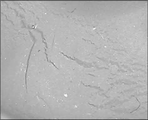
Fig. 12.7 Flow marks occur when the feedstock temperature is too low.
Fig. 12.8 Weld lines form when two cold fronts meet each other.
Most defects encountered during molding of MIM, including the ones described previously, are similar to those found in conventional plastic injection molding and are listed in Table 12.1. Also shown are the causes and remedies of these defects.
Table 12.1 Defects frequently found in molding
Defect type | Possible causes | Remedies |
Flash | Too high a pressure inside the die, poor flatness of mold surface along the parting line, venting channel too large | Use large tonnage machine, proper tool making, use a lower injection speed and molding pressure, optimize the switch point |
Sticking in cavity | Too high a molding pressure, not enough thermal shrinkage, early ejection, improper mold design, or making | Use a lower injection speed, molding/holding pressure, and mold temperature, increase cooling time, eliminate undercut and increase draft angle, adjust ejection area and location, redesign the binder |
Sink mark | Thermal shrinkage, low density | Increase molding/holding pressure and injection speed, decrease mold temperature, increase gate area, add venting channels, decrease speed when passing thick sections |
Voids | Trapped gas, absorbed moisture | Increase holding pressure, decrease injection speed, increase mold temperature, increase gate area, move gate to thick sections |
Burn marks | Overly heated binders | Decrease injection speed and feedstock temperature, increase gate area, change gate location |
Weld lines | Cold feedstock in the die | Increase injection speed, mold temperature, and feedstock temperature, enlarge gate opening, add venting channels or overflow wells near weld line locations, move gate location, redesign parts to avoid stream partition |
Flow mark | Cold feedstock in the die | Increase injection speed, mold temperature, and feedstock temperature, enlarge gate opening, change gate location |
A successful debinding process usually consists of two or three stages, during each of which one of the binder components is removed. This ensures that the shape of the molded compact remains intact throughout the debinding process. Minor binder components, such as plasticizers, surfactants, coupling agents, and lubricants, are usually removed first. Polymeric backbone binders, which account for 30%-60% of the binder, are the last type removed, and this late debinding stage is accompanied by light sintering of particles.
Several debinding processes have been identified, including the two-stage debinding process of solvent/water debinding followed by thermal debinding, straight thermal debinding, and catalytic debinding. The 100% thermal debinding is a slow process, since decomposed gas components that develop in the core section cannot escape to the atmosphere effectively through any pore channels. Defects are frequently encountered unless extremely slow heating rates and long debinding times, such as several days, are applied. Catalytic debinding is used for polyacetal-based materials, which also contain about 10% polyolefin binder components such as polyethylene and polypropylene. The polyacetal is thermally decomposed at around 135℃ into formaldehyde in a diluted nitric acid gas atmosphere. This decomposition is basically a direct solid-gas reaction. No liquid is involved and thus the compact remains rigid throughout the debinding process. Moreover, since the reaction occurs only at the binder-vapor interface, there is no internal pressure build-up caused by decomposed gases. As a result, distortion or slumping can be prevented and blistering, voids, and cracks can thus be minimized. Although catalytic debinding can produce good quality debound parts in a very short debinding period, the more widely used debinding process today is the two-stage debinding process of solvent debinding followed by thermal debinding, for economic reasons. Thus, this process will be used to illustrate the examples of debinding defects in more detail.
In the solvent debinding process, cracking and slumping are frequently observed if the process is not well executed. Since the solvent is usually heated in order to increase the debinding rate, the minor components, such as paraffin wax and lubricant, become soft or even melt. As a result, warpage and slumping frequently occur, particularly when the part has a complicated shape with overhanging sections. To alleviate this problem, using a stronger backbone binder and a lower debinding temperature is usually helpful. A modification of the part shape to give better support for thin or extended sections is also frequently employed.
When parts are subject to solvent debinding, cracking may also occur, even though the part is soft. This problem is mainly caused by the swelling of polymers when solvents penetrate into the binder. The amount of expansion depends on the temperature, and the types of binder component and solvent used. Fig. 12.9 shows the in situ length change of a 100mm long plate immersed in heptane at 40℃, 50℃, and 60℃ using a laser dilatometer. The part expands and the amount increases as the temperature increases, in particular when the temperature exceeds the melting point of a binder component. The main cause of the expansion is the reaction between the solvent and the backbone binder. This has been confirmed by using compacts with and without soluble binder components, which show similar amounts of swelling for both specimens. The addition of isopropyl alcohol reduces the amount of expansion by retarding the penetration of the heptanes. The amount of expansion also increases as the total binder content increases. These observations suggest that the solvent debinding temperature and the amount of binder should be reduced if distortion occurs.
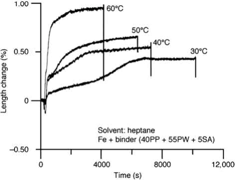
Fig. 12.9 Amount of swelling of molded specimens increases with increasing temperature.
Parts with different cross-section thicknesses also behave differently. Thin sections expand quickly in the early stage, while thick sections expand slowly, as shown in Fig. 12.10, owing to the constraints from the inner section of the part. As a result, distortion may occur early in the debinding stage because of the different amounts of expansion in different sections of the part.
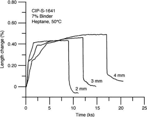
Fig. 12.10 Effect of thickness on the swelling during solvent debinding.
Debinding defects are often observed after thermal debinding. However, the causes of these defects are not necessarily related to the thermal debinding process per se. They could originate from problems in the kneading, molding, or solvent debinding processes, which are amplified and manifested during thermal debinding.
Thermal debinding defects are frequently seen when the applied heating rate is too fast. In most cases, the defects are caused by the fast decomposition of the binder components. Adsorbed water has also been shown to produce defects when it is converted to steam. When the decomposed gas molecules cannot escape fast enough to the ambient through interconnected pore channels, they cause blisters or even bloating holes if the green body is plastic. When the green body is more rigid or the interparticle friction is low, cracking will occur.
It is widely recognized that the heating rate should be slow to prevent the formation of defects. This heating rate can be determined using thermogravimetric analysis (TGA), which shows the critical temperature ranges where binder components decompose. The heating rate through these ranges should be slow or have a holding period to prevent drastic binder burn-off. However, it should be noted that the debinding behavior of parts in a production furnace with a heavy loading is quite different from that used in TGA. The temperature range where slow heating or holding is required is usually higher than that measured in TGA. It is also recommended that the gas flow rate be increased and a short flow path be used to help carry away the decomposed gases. When a vacuum furnace is used, this means that a high partial pressure should be applied during thermal debinding. The entrance and exit of the gas should be designed in such a way that the flow path over parts is short in order to maintain a laminar flow, which removes decomposed gas more effectively than does a turbulent flow.
As thermal debinding proceeds to the end, only a small amount of backbone binder is left. This remaining backbone binder is mostly located at interparticle necks. The capillary force induced tends to rearrange particles and thereby to induce internal stress. A feedstock using high tap density powder and high solids loading could help to alleviate these stresses. If the content of the backbone binder is high or the percentage of the soluble binder removed is low, distortion could occur because too much liquid binder is present during thermal debinding.
For solvent debound parts, the heating rate can be quite fast, owing to the presence of interconnected open pores. With more and larger interconnected pore channels, the gases generated during the thermal debinding can escape to the ambient without causing blistering or cracking. Fan, Hwang, Wu, and Liau (2009) used a model to predict the minimum amount of binder removal required during solvent debinding for producing interconnected pores in the middle section of products with different thicknesses. For example, to create open pores in the middle section of a part with 4.2 wt% soluble binder, the minimum debinding fraction needed is about 59% of the total amount of soluble binder, despite the thickness of the part, yielding a local debinding fraction of 37% and a porosity of 8.5% at the center. However, with too much residual binder and too few open pore channels, the large amounts of gases generated during thermal debinding may not be able to escape to the surface. Moreover, a subsequent study by the same group found that the remaining binders in the solvent debound parts redistribute within the compact during thermal debinding. As the solvent debound parts are heated previously the melting points of the binder components, capillarity drives binders into fine pore channels and interparticle contact areas in order to reduce the total surface energy. As a result, the open pores in the middle section are blocked again, as shown in Fig. 12.11. With too much binder and few interconnected pore channels, these regions behave similarly to those occurring when as-molded parts are subjected to thermal debinding directly, without solvent debinding. Thus, to improve the efficiency of thermal debinding, the amount of binder removal during solvent debinding must be increased so that the amount of the remaining binder is too little to flow into and fill in the pores in the middle section.
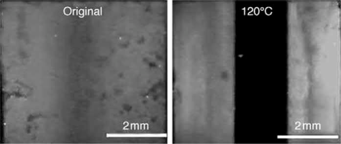
Fig. 12.11 Fluorescence dye penetration test of 6 mm thick specimens with 68% of the soluble binder removed, showing that the binder redistributes and fills open pore channels at the center of the part after being heated to 120℃.
Experimental results have shown that this minimum amount of binder removal for the prevention of binder redistribution increases as the thickness of the part increases.For parts with 4.20 wt% soluble binder and a thickness of 6mm, the suggested minimum amount of binder removal for solvent debinding is 79%, or 3.32 wt% of the total weight of the part, when a heating rate of 5℃/min is used. This value is higher than the 59% required for creating open pores in the center of the part during solvent debinding. Since the minimum amount of the binder that needs to be removed depends on the thickness of the part and the heating rate of the thermal debinding, a general number of 90% is recommended for a safe start.
The exfoliation phenomenon, which is caused by the delamination of a skin layer from the main body, has also been reported. This has been attributed to the binder-rich surface caused by incorrect molding procedures in combination with a fast heating rate during thermal debinding. One postulation is that, as the feedstock cools in the die cavity, the material shrinks owing to the volume shrinkage of the metal powder and binder components, in particular the paraffin wax. This shrinkage leaves a small clearance between the part and the die wall, which allows further penetration of the feedstock. Since the clearance is small, the easiest material to fill this gap in the pressure holding stage of the molding process is the low melting material, such as paraffin wax. The other possibility causing the binder-rich surface is the increased binder/powder ratio at the surface due to the emerging flow of the binder from the interior during thermal debinding. With a high binder content and less interparticle friction, a layer, or skin, could detach from the main body. With a fast heating rate, this phenomenon may worsen if the outward flow of the binder is accelerated by the high pressure of the decomposed gas in the core of the part.
To facilitate explanation, Table 12.2 presents a summary of the various types of defects found after solvent and thermal debinding, the possible sources of the problems, and the recommendations for their removal.
Table 12.2 Defects frequently found in debinding
Defect type | Possible causes | Remedies |
Cracks (solvent debinding) | Swelling of binder components, poor bonding between binder and powder, low strength of the backbone binder, too high a molding pressure, large differences in section thicknesses | Change the type and composition of solvent or binder, use a lower injection speed and molding pressure, redesign parts with smaller differences in section thicknesses, use lower debinding temperatures |
Bending/distortion (solvent debinding) | Residual stress from molding, lack of support for overhanging sections, entrapped air | Bake between 50℃ and 90℃, usefixtures, adjust molding parameters |
Corrosion/stain (solvent debinding) | High acidity of solvent, humid environment | Replenish solvents or use new ones, leave parts in a dry atmosphere |
Cracks/blistering (thermal debinding) | Overly fast heating, absorbed water in feedstock, insufficient binder removal for solvent debinding, poor binder distribution, low solid content | Use slow heating rates, extend solvent debinding time, use longer kneading time and adjust binder components, keep feedstock dry, use higher gas sweeping rate and shorter flow path |
Bending/distortion (thermal debinding) | Overly fast heating, insufficient binder removal for solvent debinding, lack of support for overhanging sections, insufficient interparticle friction, too much binder | Use slow heating rates, extend solvent debinding time, use fixtures or sands for the support, use higher gas sweeping rate, use more irregular powders, increase solids loading |
Exfoliation (thermal debinding) | Wax separation to the surface, overly high heating rate | Extend solvent debinding time, use slower heating rate, bake below 100℃ |
Several techniques have been developed to alleviate the previously mentioned defects of cracking, blistering, and distortion that occur during thermal debinding. They include the use of slow heating rates in the temperature range where binder components decompose or evaporate, high gas flow rates, higher binder removal percentages during solvent debinding, and supports or fixtures for overhanging and intricate sections. The use of more irregular powders also helps to increase the green strength and allows the use of a faster debinding rate. However, these powders will have an adverse effect on feedstock flowability and sinterability.
The binder residues left from debinding have been paid little attention in the literature. These residues could be critical for some structural or magnetic parts. Oxide residues from high-density polyethylene and metal stearates have been reported in several studies. These oxides may come from catalysts, which are used as Ziegler-Natta initiators for polymerization of polyethylene and isostatic polypropylene, while some other oxides may come from metal atoms in stearates. The metal atoms can usually be dissolved in the matrix during sintering. However, reactive metals such as titanium and aluminum will react with oxygen or water vapor in the metal powder or sintering atmosphere, forming stable metal oxides. These oxides or dissolved elements could influence the mechanical properties of structural parts. These residues may not always be detrimental to MIM parts. It has been demonstrated that residual Ti from high-density polypropylene helps densification and increases the strength. Magnesium from magnesium stearate has also been shown to improve the sintered density and bending strength of injection molded alumina by forming fine and uniformly distributed magnesia in the alumina matrix.
Another residue is carbon soot left from thermal debinding. With an increase in the carbon content, the corrosion resistance of stainless steels such as 316L will deteriorate due to the formation of chromium carbide and Cr-lean areas. If an excessive amount of carbon is present, the melting point decreases and may cause local distortion or melting of the part. For Kovar (Fe-29Ni-17Co), the coefficient of thermal expansion will also increase and cause adverse effects on glass-metal sealing (Tokui et al., 1994). To ensure complete debinding without leaving carbon residues, a high gas sweeping rate during thermal debinding is recommended. With the use of continuous furnaces, such as pusher or walking beam furnaces, a high dew point in the debinding zone is also recommended to facilitate the removal of the carbon residues. It should be noted that carbon has a high diffusion rate into iron and that such diffusion starts at about 875℃, depending on the carbon content and the phase transformation temperature. Thus, thermal debinding and carbon removal should be completed before parts reach this temperature.
One of the advantages of the MIM process is its capability to produce parts with shiny surface finishes that have small surface roughness. To achieve this goal, high density must be obtained, and the metal surface must be free from reaction with sintering atmospheres to avoid the formation of oxides, nitrides, or other reaction products. Consequently, the dew point or oxygen content in the atmosphere must be sufficiently low, and the amount of hydrogen or the degree of vacuum must be sufficiently high, to reduce the metal oxides on metal powder surfaces. Otherwise, fine oxide particles, such as silicon dioxides, can easily form. When nitrogen is contained in the atmosphere, such as dissociated ammonia, it will react with the chromium in stainless steels, forming chromium nitrides, which deteriorate the corrosion resistance of stainless steel. When a high vacuum is used at high temperatures, chromium will evaporate, with a resultant reduction in corrosion resistance. Thus, a partial atmosphere of argon or pure argon is often used for high-temperature sintering. These sintering concerns and solutions are similar to those for press-and-sinter parts.
High density, above 95% of the theoretical density, is usually required for MIM parts. To achieve this density, fine powder and high-temperature sintering are used most of the time. In some cases, liquid phase sintering, including supersolidus liquid phase sintering, is required. Unfortunately, with the typically low solids loading in MIM parts, less than 70 vol%, preservation of the geometry is a challenge. This problem is an even greater challenge in prealloyed powders for which the solidus and liquidus lines are flat and the temperature difference between these two lines is small. These characteristics make the amount of liquid very sensitive to the temperature variation in the sintering furnace, as indicated by the phase diagram and the lever rule. A good example is the SKD11 or D2 tool steels. The temperature must be controlled to within ±5℃. If the temperature is too high, too much liquid is formed; then gravitational forces cause distortion or even slumping, while too small an amount of the liquid will not densify the compact.
Several solutions have been reported. A recent patent discloses prealloyed tool steel powders doped with 2%-5% niobium. The niobium forms NbC and inhibits grain growth during liquid phase sintering. With fine grains, the thickness of the liquid layer at the grain boundaries decreases, which makes particle rearrangement more difficult. The addition of carbides has also proven effective to open up the sintering window with the same underlying mechanism.
Similar to the distortion problems found in solvent debinding, overhanging sections, steps, and narrow openings, as shown in the schematic diagram of Fig. 12.12, may also distort during sintering due to gravitational force or uneven amounts of shrinkages in different regions. This problem becomes even more serious when liquid phase sintering or heavy metals such as tungsten alloys are used. The use of high solids loading and more irregular powders helps to a certain degree. But sintering fixtures are often required to prevent warping, and dummy bridges, which are removed by mechanical methods after sintering, are often designed into the part to prevent opening or narrowing of the long slots during sintering.
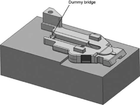
Fig. 12.12 Parts with long overhangs, steps, and slots require sintering fixtures and dummy bridges to prevent sagging and opening/closure of the slots
Although considerable time and effort has been spent to resolve the problems encountered during the fabrication of MIM parts, and the technology itself has advanced significantly since the birth of the MIM process, defects still frequently occur during the daily practices of kneading, injection molding, debinding, and sintering. Some examples are gate marks, sink marks, distortions, cracking, blistering, and poor dimensional control. Some of these problems have been resolved, and the underlying basics are understood, as briefly described previously. However, many challenging problems remain, and in-depth understanding of the root causes and the fundamentals of the processes has yet to be attained. There is still much to learn about the residual stress in molded articles, powder/binder separation, the flow behaviors of binders during molding, binder redistribution behavior during thermal debinding, and shape retention during supersolidus liquid-phase sintering.
Contact: Cindy Wang
Phone: +86 19916725892
Tel: 0512-55128901
Email: [email protected]
Add: No.6 Huxiang Road, Kunshan development Zone, JiangsuShanghai Branch: No. 398 Guiyang Rd, Yangpu District, Shanghai, China